
Fluid monitoring and sampling apparatus

Inactive Publication Date: 2005-09-29
YEKUTIELY DAVID +1
View PDF4 Cites 14 Cited by
  • Summary
  • Abstract
  • Description
  • Claims
  • Application Information

AI Technical Summary

Benefits of technology

[0003] The present invention seeks to provide a novel fluid level monitor (or gauge, the terms being used interchangeably herein) that can be used for real-time monitoring of water level and properties in a well and the like, as is described more in detail hereinbelow. Although the present invention is des

Problems solved by technology

It is readily understood that such a situation is undesirable and intolerable.
The sand that is pumped with the water can foul and damage irrigation pumps of agricultural consumers.
The quality of water mixed with seawater is intolerable and dangerous for drinking purposes.
Unfortunately, the prior art has no known solution for real-time monitoring of water level in a well, especially deep wells.

Method used


Image

  • Fluid monitoring and sampling apparatus
  • Fluid monitoring and sampling apparatus
  • Fluid monitoring and sampling apparatus

Examples


Embodiment Construction

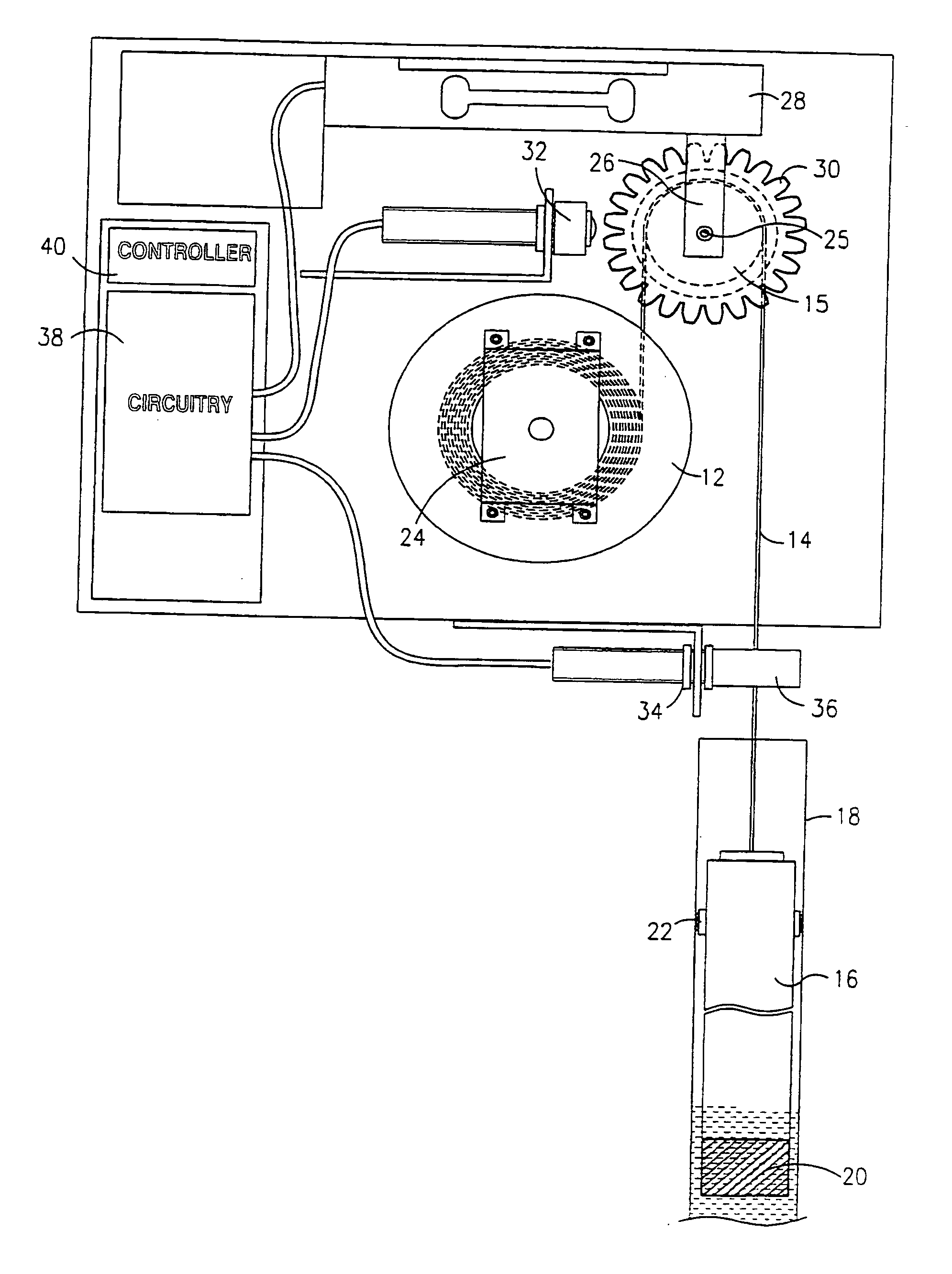
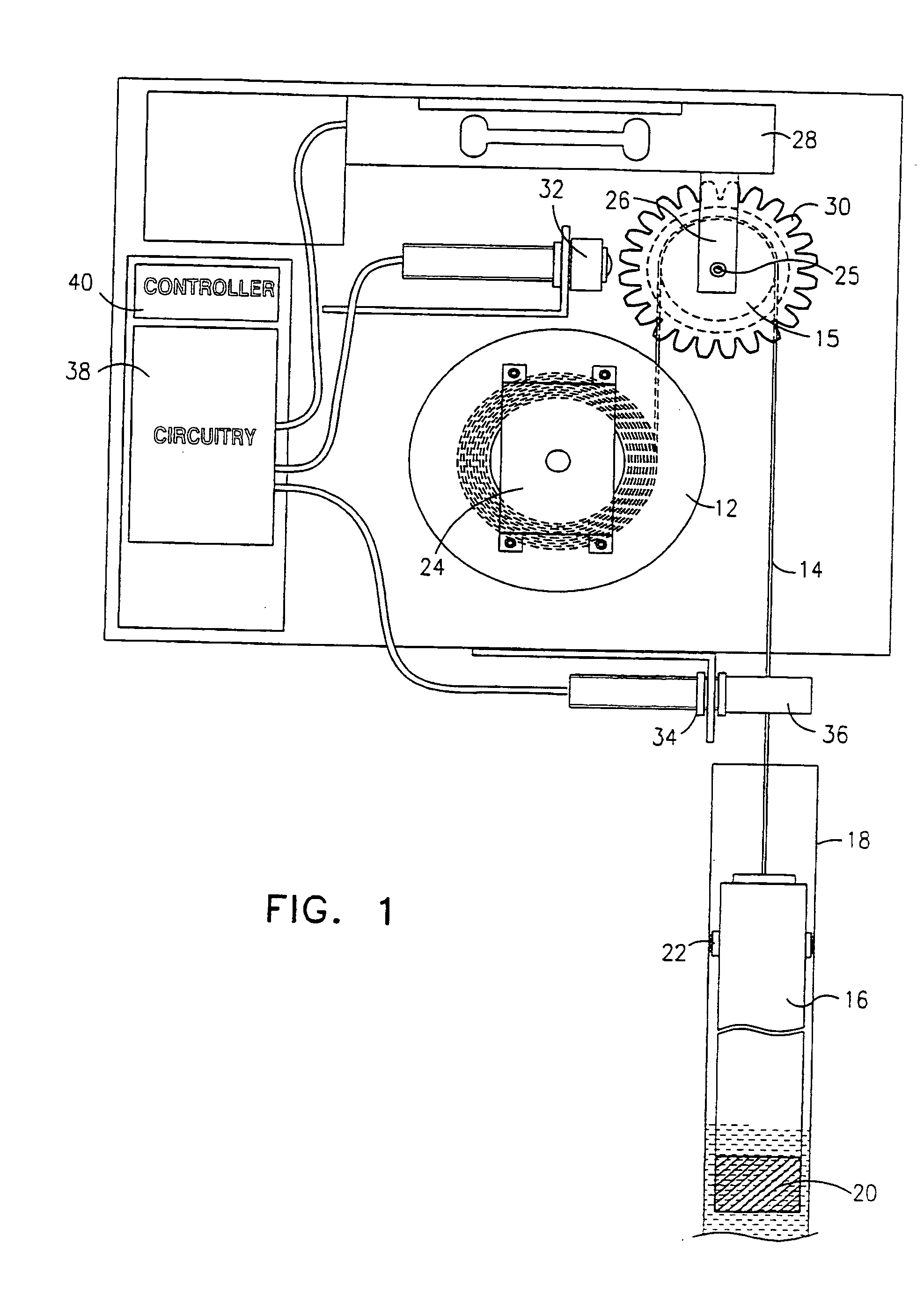
[0009] Reference is now made to FIG. 1, which illustrates fluid level monitor 10 constructed and operative in accordance with a preferred embodiment of the present invention.

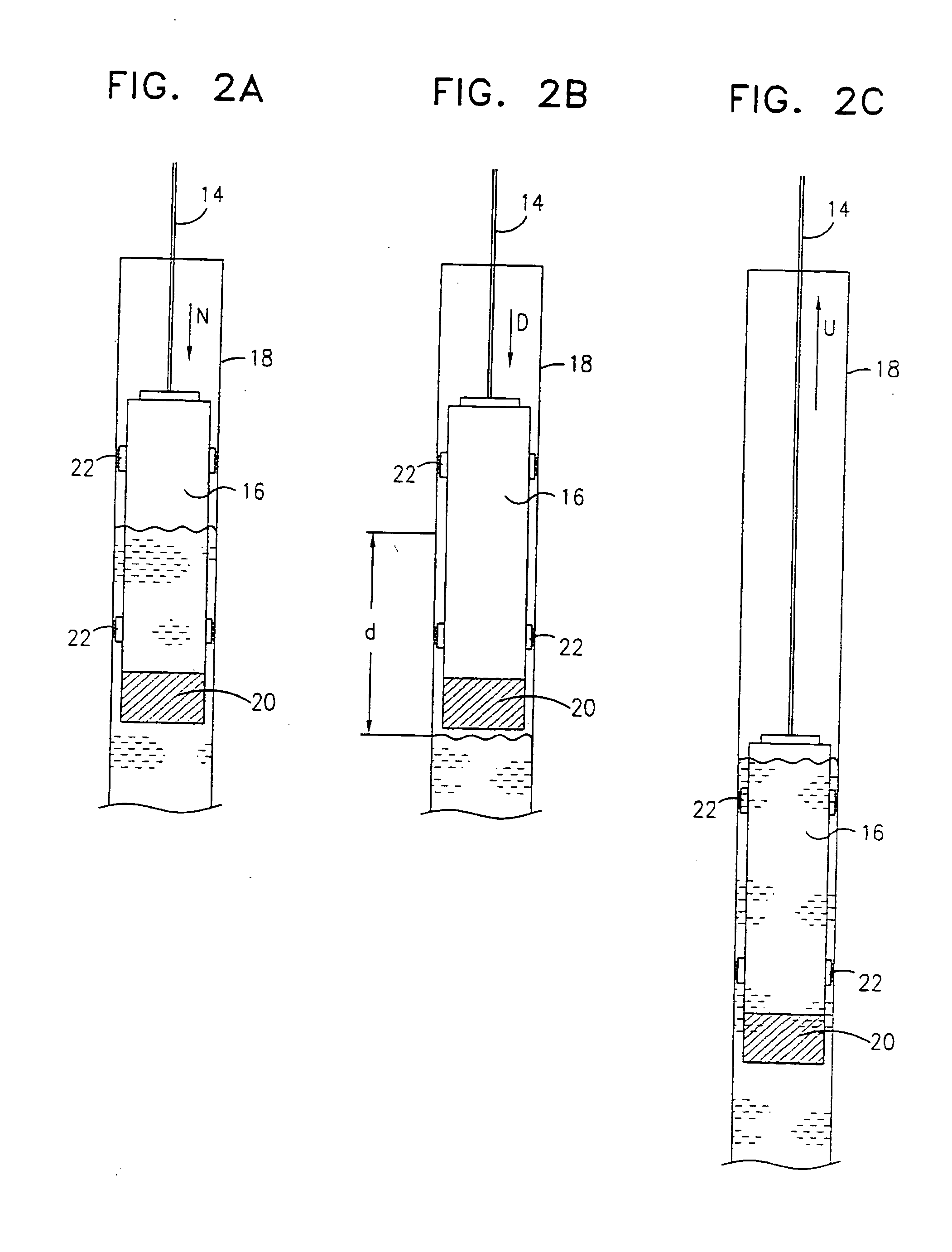
[0010] Fluid level monitor 10 preferably includes a spool 12 of a filament 14. The term “filament” encompasses any string, thread, fishing line, cord, wire or rope and the like. Filament 14 is preferably wrapped one or more times around a bobbin 15, and an end of filament 14 is attached to a buoyant element 16. Buoyant element 16 is preferably disposed inside a generally vertical elongate tube 18. Such a tube is generally installed in most water wells for testing and sampling purposes, and runs virtually the entire depth of the well. The present invention exploits the fact that such a tube is present in water wells, and that such a tube offers a clean, generally undisturbed environment for buoyant element 16.

[0011] Buoyant element 16 may be fashioned in the form of a generally hollow cylinder with a weight 20 ...


PUM


Abstract

Fluid monitoring and sampling apparatus including a buoyant element suspended from a filament, a load sensor that senses a tensile force in the filament, a rotation sensor that senses the rotation of the spool around which the filament is wound, wherein the buoyant element is adapted to be initially at least partially submerged at an equilibrium position at an initial level of a fluid, thereby creating a nominal tensile force in the filament, wherein a change in the level of the fluid changes the tensile force in the filament, a positive change in the tensile force corresponding to a downward movement of the buoyant element and a negative change in the tensile force corresponding to an upward movement of the buoyant element, wherein the rotation of the spool corresponds to an amount of distance traveled by the buoyant element, and a sensor for sensing a property of the fluid, the sensor being in communication with a processor above ground.

Description

FIELD OF THE INVENTION [0001] The present invention relates generally to fluid level gauges or monitors, and particularly to a fluid level gauge or monitor for use with water or fuel wells, and the like. BACKGROUND OF THE INVENTION [0002] In many localities, water is supplied to consumers by pumping the water from wells. Water wells can be quite deep, some reaching depths of over 500 meters. In states or countries that have low amounts of precipitation, well water is a precious commodity, and wells are intensively pumped to meet the consumer demand. In such cases, the level of the water in the well can reach low levels, and the pumped water can become mixed with sand or seawater. It is readily understood that such a situation is undesirable and intolerable. The sand that is pumped with the water can foul and damage irrigation pumps of agricultural consumers. The quality of water mixed with seawater is intolerable and dangerous for drinking purposes. It is thus imperative to monitor ...

Claims


Application Information

Patent Timeline
IPC IPC(8): G01F23/36G01F23/40G01F23/44G01N1/10G01N1/12G01N9/00G01N9/12G01N11/00G01N33/00
CPCG01F23/40G01F23/44G01N1/12G01F23/0038G01N11/00G01F23/0023G01N9/00
Inventor YEKUTIELY, DAVIDYEKUTIELY, BARAK
Owner YEKUTIELY DAVID
Learn More