
Demodulation apparatus and method using code table that decreases complexity

a demodulation apparatus and code table technology, applied in the field ofsignal demodulation technology, can solve the problems of app decoding table becoming remarkably complicated, time required for calculating an llr,

Inactive Publication Date: 2005-09-22
SAMSUNG ELECTRONICS CO LTD
View PDF8 Cites 1 Cited by
  • Summary
  • Abstract
  • Description
  • Claims
  • Application Information

AI Technical Summary

Benefits of technology

[0024] The present invention provides a demodulation apparatus and method using a code table in a soft demodulator, which decreases complexity and increases demodulation efficiency.
[0025] The present invention also provides a demodulation apparatus and method using a code table which decreases complexity in order to obtain soft demodulation results of a run-length limited (RLL) code.
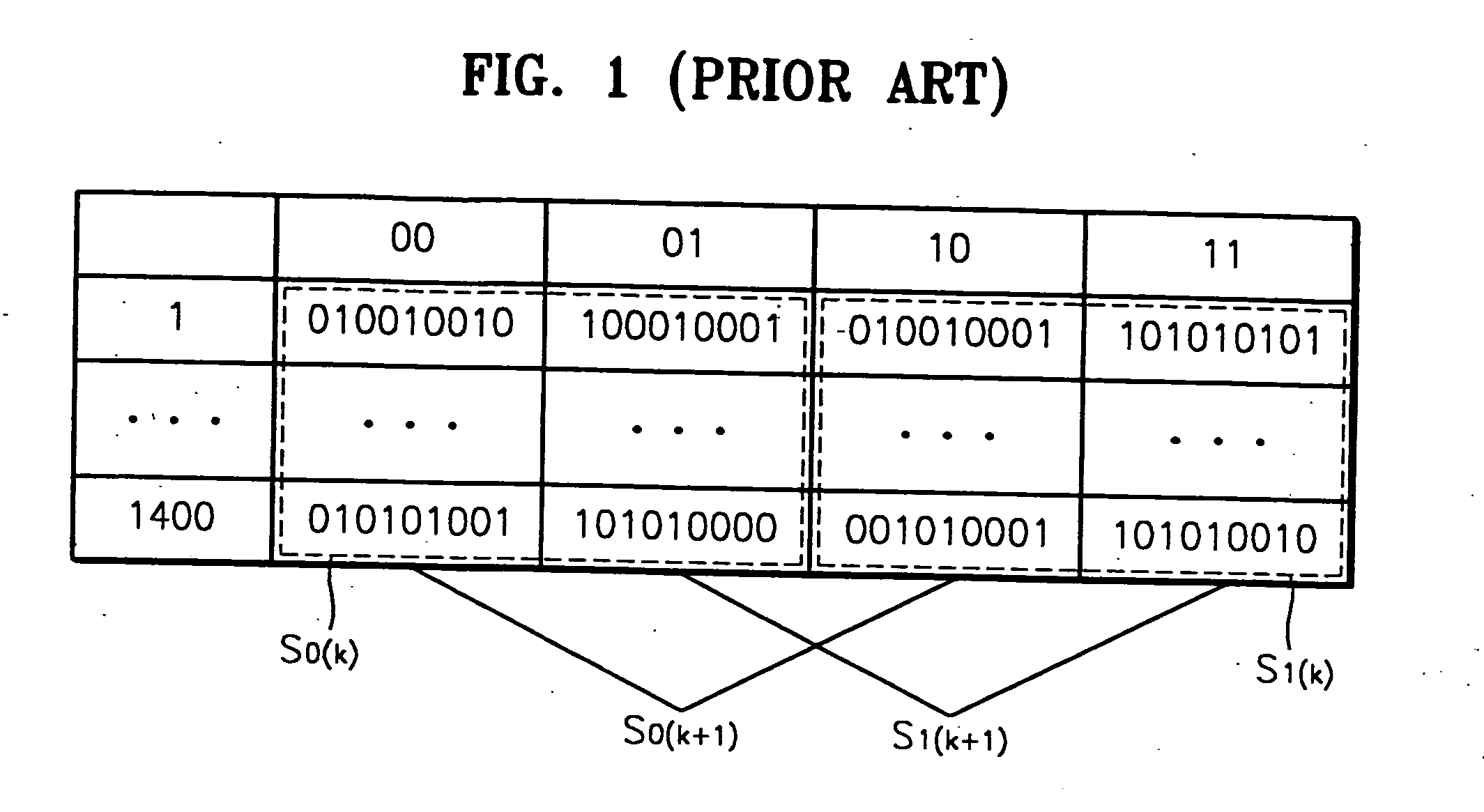
[0027] According to an aspect of the present invention, there is provided an apparatus which demodulates a code word having a second predetermined bit length greater than a first predetermined bit length, the code word resulting from modulation of a data word having the first predetermined bit length. The apparatus includes a code table comprising a plurality of the code words, wherein similar ones of the code words are arranged to be grouped together; and a soft demodulator to calculate probabilities of individual bits that constitute the code words, and to generate a soft demodulation value of the data word.
[0028] According to another aspect of the present invention, there is provided a method of demodulating a code word having a second predetermined bit length greater than a first predetermined bit length, the code word resulting from modulation of a data word having the first predetermined bit length. The method includes using a code table comprising a plurality of code words, wherein similar ones of the code words are arranged to be grouped together; and calculating probabilities of individual bits that constitute the code words, and generating a soft demodulation value of the data word.

Problems solved by technology

As described above, when the size of an APP decoding table used in the conventional soft demodulator increases, the time required for calculating an LLR also increases, and the APP decoding table becomes remarkably complicated.

Method used


Image

  • Demodulation apparatus and method using code table that decreases complexity
  • Demodulation apparatus and method using code table that decreases complexity
  • Demodulation apparatus and method using code table that decreases complexity

Examples


Embodiment Construction

[0034] Reference will now be made in detail to the present preferred embodiments of the present invention, examples of which are illustrated in the accompanying drawings, wherein like reference numerals refer to the like elements throughout. The embodiments are described below in order to explain the present invention by referring to the figures.

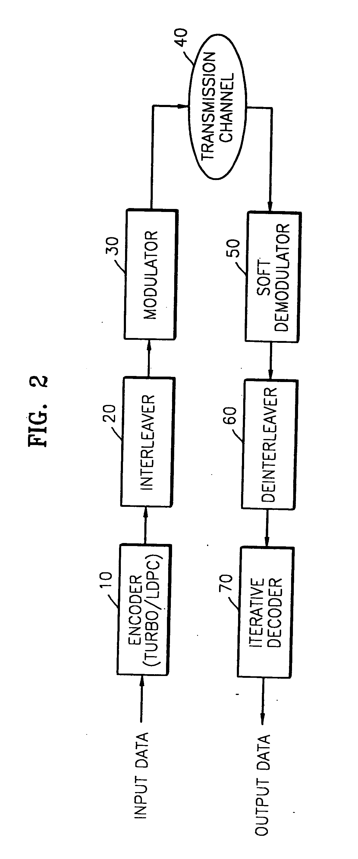
[0035] Referring to FIG. 2, a system which applies the present invention includes an encoder 10, an interleaver 20, a modulator 30, a transmission channel 40, a soft demodulator 50, a deinterleaver 60, and an iterative decoder 70. However, various modifications can be made to the system. For example, the interleaver 20 and the deinterleaver 60 may not be provided, or a soft channel detector, between the transmission channel 40 and the soft demodulator 50, may be further provided.

[0036] The encoder 10 encodes input data using predetermined soft encoding, such as Low Density Parity Check (LDPC) coding and / or turbo coding, for error correctio...


PUM

PropertyMeasurementUnit
run-lengthaaaaaaaaaa
densityaaaaaaaaaa
run-length limitedaaaaaaaaaa

Abstract

A demodulation apparatus and method using a code table that decreases complexity. The demodulation apparatus includes a code table including a plurality of the code words, wherein similar ones of the code words are arranged to be grouped together; and a soft demodulator to calculate probabilities of individual bits that constitute the code words, and to generate a soft demodulation value of the data word.

Description

CROSS-REFERENCE TO RELATED APPLICATIONS [0001] This application is a continuation of application Ser. No. 10 / 729,993 filed on Dec. 9, 2003, now pending. The content of application Ser. No. 10 / 729,993 is hereby incorporated herein by reference in their entirety. [0002] This application claims the benefit of Korean Patent Application No. 2002-81028, filed on Dec. 18, 2002, in the Korean Intellectual Property Office, the disclosure of which is incorporated herein by reference.BACKGROUND OF THE INVENTION [0003] 1. Field of the Invention [0004] The present invention relates to signal demodulation technology, and, more particularly, to a demodulation apparatus and method using a code table in a soft demodulator, which decreases complexity and increases demodulation efficiency. [0005] 2. Description of the Related Art [0006] Generally, in an environment utilizing high-density optical recording media, inter symbol interference (ISI) exists, and data is modulated using run-length limited (RL...

Claims


Application Information

Patent Timeline
Patent Type & Authority Applications(United States)
IPC IPC(8): G11B20/10H03M7/14H03M7/46H03M13/27H03M13/39H03M13/45
CPCG11B20/10009H03M7/46
Inventor HAN, SUNG-HYUKIM, KI-HYUNPARK, IN-SIKLEE, YOON-WOO
Owner SAMSUNG ELECTRONICS CO LTD
Learn More