
Tunable suspension system for enhanced acceleration characteristics of wheeled vehicles

Inactive Publication Date: 2005-09-22
GIBSON GREGORY RAY +1
View PDF0 Cites 26 Cited by
  • Summary
  • Abstract
  • Description
  • Claims
  • Application Information

AI Technical Summary

Benefits of technology

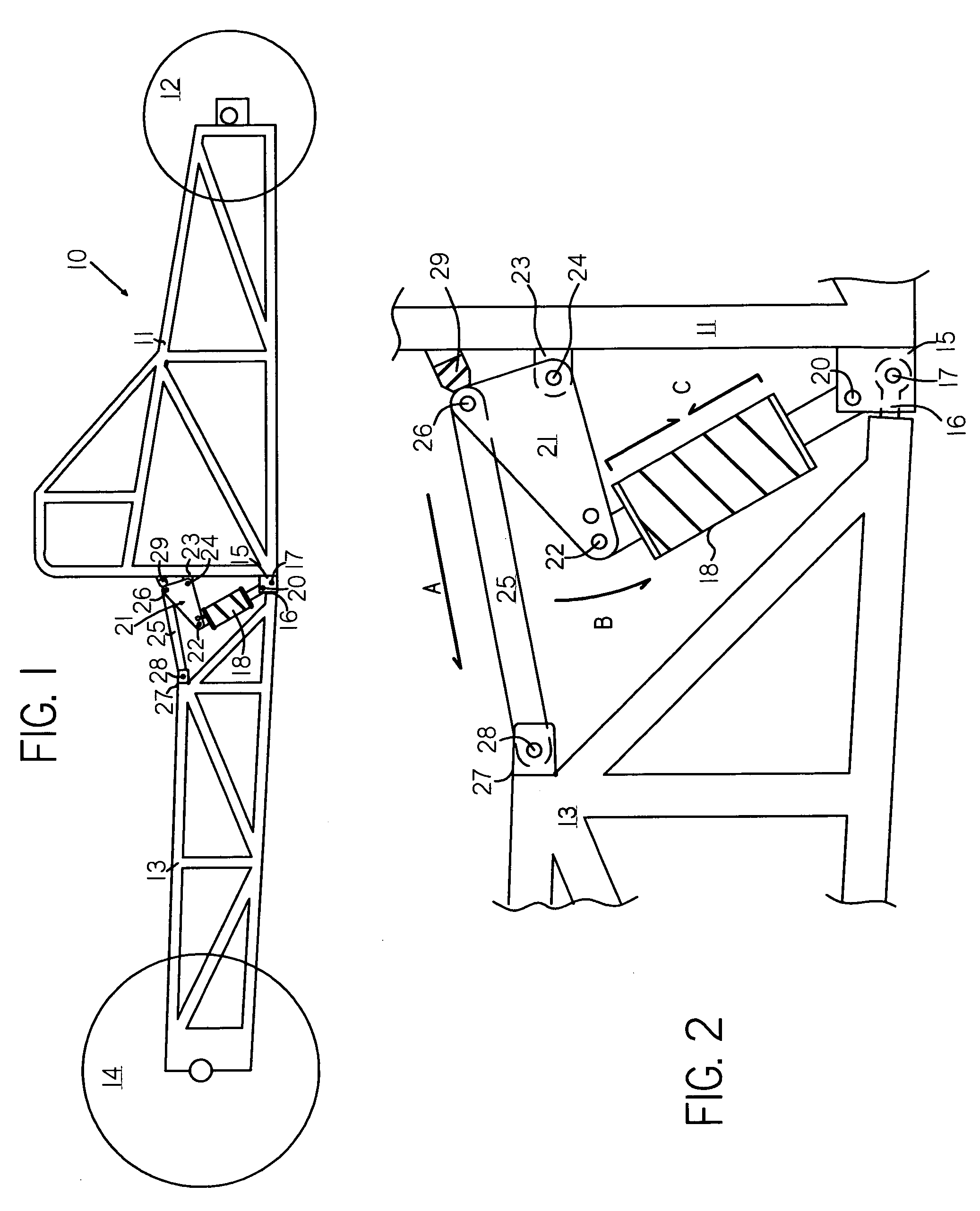
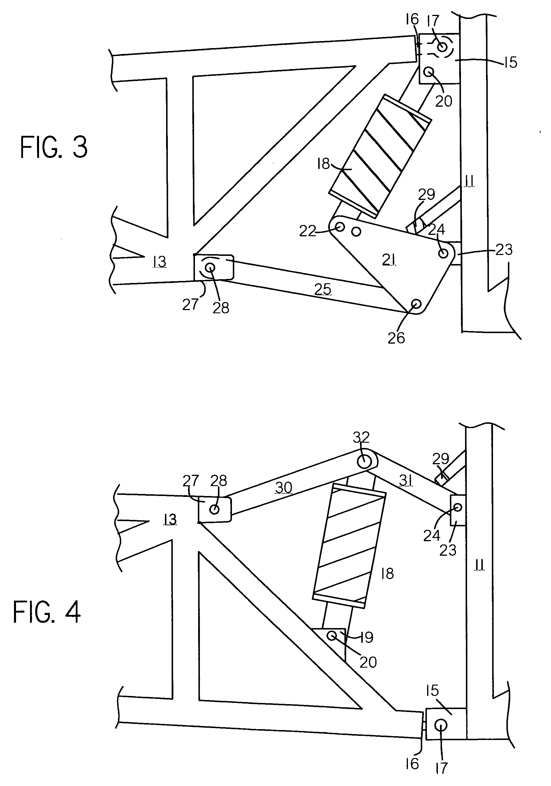
[0012] The invention is an improved suspension system for a wheeled vehicle which allows controlled and adjustable center of gravity height change upon acceleration, such that a skilled operator may tune or adjust the dynamic weight transfer characteristics exhibited by a vehicle upon rapid acceleration so as to optimize the acceleration of the vehicle under varying vehicle, road surface, and environmental conditions. The invention utilizes two substantially rigid frame structures (collectively referred to as the chassis), the front connected to one or more front wheels, and the rear connected to one or more driven rear wheels, the two frame structures being connected by fixed pivot points which allow rotation about an axis which is horizontal and perpendicular to the centerline of the vehicle and located relatively near the longitudinal center of gravity and major masses of the vehicle; further having one or more damped springs, with dampening, spring rate, and spring preloading being adjustable, oriented such that the amount and rate of upward rotational moment and upward motion of the central masses of the vehicle on acceleration, and corresponding dynamic change in center of gravity height, are resisted by the spring and dampener to an extent which is quickly and easily adjustable. This invention thus provides for a large range of controlled adjustment of the dynamic center of gravity height, upward chassis rotational moment, and rearward weight transfer, such that the factors such as varying engine output, track surface coefficient of friction, temperature, and climactic conditions can be controlled for in order to obtain the greatest, most predictable, and most consistent acceleration of the vehicle with a minimum of upsetting influences.
[0013] The invention also provides ancillary benefits such as highly damped and minimal chassis oscillation with resulting superior down-track traction, driver confidence, and increased chassis life; and the ability of a vehicle designer or builder to mimic longer wheelbase vehicle launch with a shorter wheelbase vehicle with its inherent advantages. Maximum weight transfer to the rear wheels may be attained with less chance of the potentially unsafe and damaging extreme front wheel lift often experienced by shorter wheelbase, traditionally suspended cars, yet with a much greater range of adjustment than ordinarily attainable by long wheelbase dragsters. Although it would be a significant improvement on a long or short wheelbase vehicle, our invention would necessarily have a greater range of adjustability when properly matched to the characteristics and wheelbase of any particular vehicle, e.g. for best results the preferred embodiment for a rear-engined roadster would contemplate a wheelbase of 120 to 150 inches and appropriate static center of gravity height. The orientation of spring resistance of the invention also provides for damped spring assist in returning the vehicle to its desired ride height, which has aerodynamic and stability advantages for most vehicles at higher speeds.

Problems solved by technology

Unfortunately, the vehicle dynamics with these systems can be extremely complex with a great number of sometimes conflicting variables (a competition four-link rear suspension might have well over a hundred potential link geometries), such that tuning or “setting up” the vehicle for varying track conditions can be very difficult or impractical under competition conditions.
Also, because of their relatively short wheelbase and limited static rear weight distribution, these traditionally suspended cars must often utilize relatively high static center of gravity, such that if the suspension is not balanced precisely the vehicle may lift the front wheels excessively on launch, potentially creating situations which are unsafe and damaging to the vehicle.
Very long wheelbase (180 inch plus), often rear-engined dragsters with solidly mounted front and rear axles were developed in an attempt to eliminate such variables; but while the resulting vehicles certainly have less complexity than traditionally suspended vehicles, they suffer from certain inherent variables of their own.
The primary drawbacks of relying upon inherent frame flex to assist rearward weight transfer on launch are that it provides for a very limited adjustability of the total amount of chassis flex or rotational moment about the rear axle centerline (and thus dynamic center of gravity increase and rearward weight transfer); and further the chassis flex is typically undamped, such that the original launch or any subsequent track undulations will set up significant bending oscillations in the chassis which can upset the driven tire loading and the driver's concentration to the detriment of the vehicle's total acceleration capabilities, consistency, and predictability, and could conceivably result in an accident or frame damage.
Some have attempted to place front-engined vehicle derived suspension systems, such as four-link systems, on the rear of dragsters, but while having the last 18 inches or so separately sprung could serve to diminish uncontrolled chassis oscillation by disrupting certain oscillation harmonics, the vast majority of the frame remains an undamped spring such that undesirable and uncontrollable chassis movement is likely to continue; while the extreme long wheelbase and severe mechanical limitations on the ability of the rear axle to move in relation to the rest of the frame dictate that the ability to meaningfully adjust the dynamic center of gravity and rearward weight transfer change is dubious.
Others have used frames with unwelded portions, “slip-tubes,” in an attempt to permit greater range of adjustment, but such systems rely solely on friction for partial dampening effect, and achieving consistent and predictable tunability from variations in clamping of tubes, particularly in a competition setting, can be problematic at best.
This suspension system could have some beneficial effect on dampening down track bumps, but its range of adjustability on what remains very long, relatively flexible frames limits its effectiveness.
If the central spring is stiffened so greatly as to be nearly rigid, the device is ineffective and the dragster will behave as any other dragster with uncontrolled oscillation.
To the extent the central spring is softened, the vehicle will have oscillations which, while more damped, are potentially of an even greater magnitude than a standard dragster which could lead to the center of the very long wheelbase vehicle bottoming on the ground and generally continued disruption of driven tire loading, the vehicle, and its driver.
Because of the very long wheelbase (and relatively flexible frames) of the vehicles contemplated in U.S. Pat. No. 05,630,607, the fact that the suspension spring(s) are not oriented to variably resist upward chassis movement, and the damper(s) are not adjustable to varying stiffnesses, significant adjustability of the dynamic center of gravity height and rearward weight transfer change remains poor at best.

Method used


Image

  • Tunable suspension system for enhanced acceleration characteristics of wheeled vehicles
  • Tunable suspension system for enhanced acceleration characteristics of wheeled vehicles
  • Tunable suspension system for enhanced acceleration characteristics of wheeled vehicles

Examples


Embodiment Construction

[0021] The invention is an improved suspension system for a wheeled vehicle which allows controlled and adjustable center of gravity height change upon acceleration, such that a skilled operator may tune or adjust the dynamic weight transfer characteristics exhibited by a vehicle upon rapid acceleration so as to optimize the acceleration of the vehicle under varying vehicle, road surface, and environmental conditions. The invention utilizes two substantially rigid frame structures (collectively referred to as the vehicle frame), the front connected to one or more front wheels, and the rear connected solidly to one or more driven rear wheels, the two frame structures being connected by fixed pivot points which allow rotation about an axis which is horizontal and perpendicular to the centerline of the vehicle and located relatively near the longitudinal center of gravity and major masses of the vehicle; further having one or more damped springs, with dampening, spring rate, and spring...


PUM


Abstract

An improved vehicle suspension system providing for readily adjustable rearward weight transfer upon acceleration by permitting controlled upward motion of the mid-wheelbase portion of the vehicle and corresponding dynamic change in center of gravity height. The movement of the central portions of the vehicle in an upward direction is controlled and adjusted through a plurality of pivot points and links, together with variable resistance spring and damper means, to provide for optimum dynamic weight transfer onto driven wheels and superior acceleration characteristics under a variety of road surface, vehicle, and environmental conditions.

Description

CROSS-REFERENCE TO RELATED APPLICATIONS [0001] The present application claims priority from Applicants' co-pending U.S. provisional application, Ser. No. 60 / 543,669, filed Feb. 12, 2004.STATEMENT REGARDING FEDERALLY SPONSORED RESEARCH OR DEVELOPMENT [0002] Not Applicable. BACKGROUND OF THE INVENTION [0003] 1. Field of the Invention [0004] This invention relates to a suspension system for a wheeled vehicle. [0005] More particularly, this invention relates to a suspension system allowing controlled and adjustable center of gravity height change upon acceleration, such that a skilled operator may tune or adjust the dynamic weight transfer characteristics exhibited by a vehicle upon rapid acceleration so as to optimize the acceleration of the vehicle under varying vehicle, road surface, and environmental conditions. [0006] 2. Description of the Prior Art [0007] Typical front-engined, rear wheel drive drag racing cars have suspension systems derived from the automotive and racing industr...

Claims


Application Information

Patent Timeline
IPC IPC(8): B60P1/00
CPCB60G11/006B60G2300/07B60G2300/27B62D53/02B62D21/183B62D23/005B60G2300/40
Inventor GIBSON, GREGORY RAYMUNSON, DONALD CLAUDE
Owner GIBSON GREGORY RAY
Learn More