
Integrated thin high temperature heaters

a heater and high temperature technology, applied in the field of integrated heaters, can solve the problems of limiting the utility of these materials, unable to be attached directly to metal, and viable high temperature, and achieve the effect of efficient thermal transfer

Inactive Publication Date: 2005-09-22
OLDING TIM +2
View PDF2 Cites 13 Cited by
  • Summary
  • Abstract
  • Description
  • Claims
  • Application Information

AI Technical Summary

Benefits of technology

[0007] This invention is an integrated thin heater design has been designed with a suitable electrically insulating layer to separate the thin heating element from the conductive substrate material. This insulating layer is able to provide both electrical insulation and efficient thermal transfer.
[0008] This resulting integrated heater is able to meet the regulatory electrical insulation requirements and is capable of operation in excess of 600° C. The heating element can also survive being repeatedly thermally cycled between room temperature and the specified operating temperature.

Problems solved by technology

However the cost of the silver materials and the processing requirements limit the utility of these materials.
This approach is extremely versatile and cost effective, but is limited in its temperature of operation to below 400° C.
However, simply attaching a foil to another material in general does not result in a viable high temperature, heating element.
Obviously it cannot be attached directly to metal or it would short out.
Alternatively, the resistive foil cannot be in direct contact with glass because most glasses become conductive at high temperatures.
However, these designs do not meet the industry acceptance tests due to the fact that the glass ceramic becomes conductive at 200° C. Fixing an element in direct contact with the glass ceramic results in a unit that does not meet the regulatory standards for electrical safety.

Method used


Image

  • Integrated thin high temperature heaters
  • Integrated thin high temperature heaters
  • Integrated thin high temperature heaters

Examples


example 1

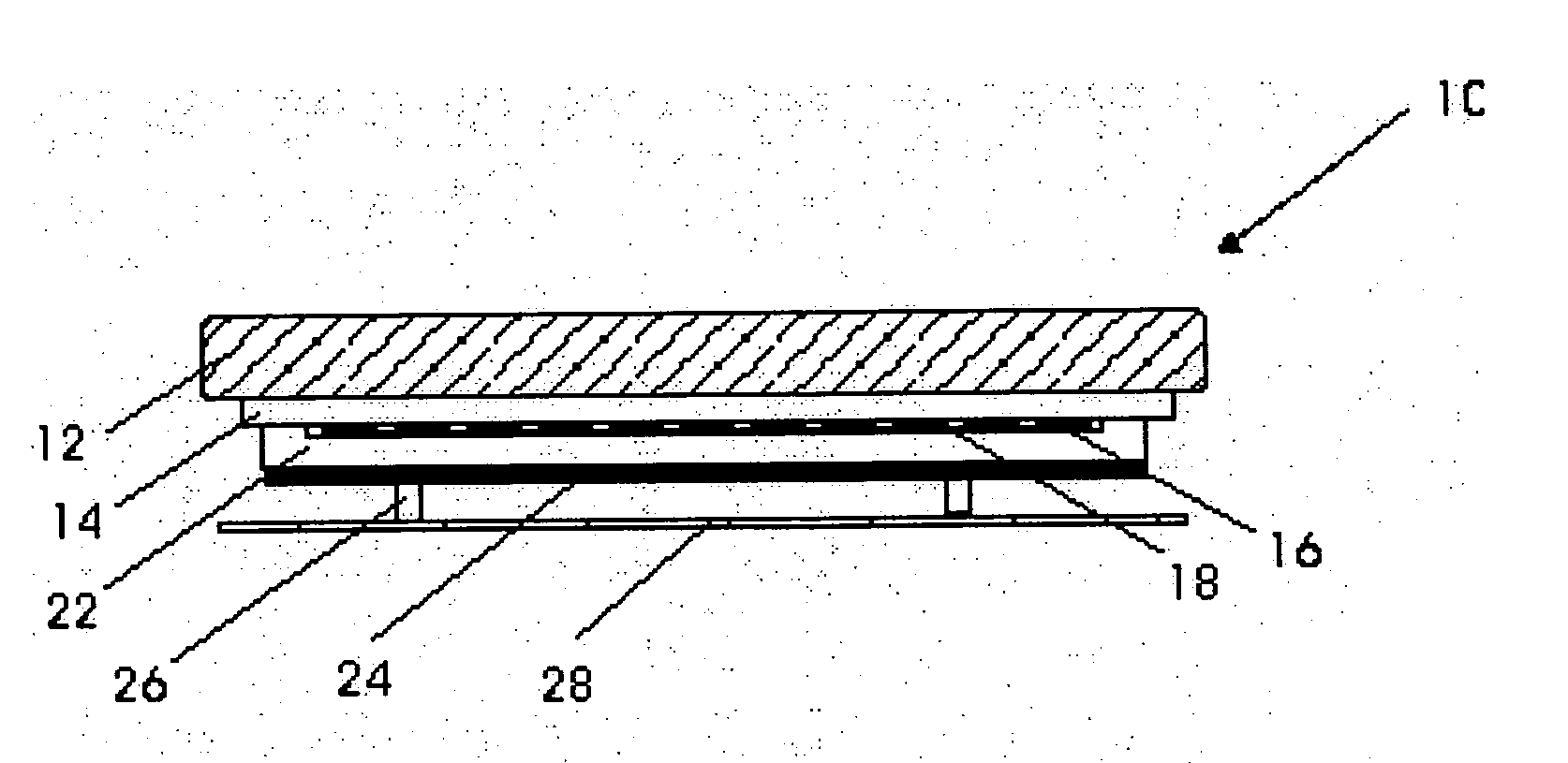
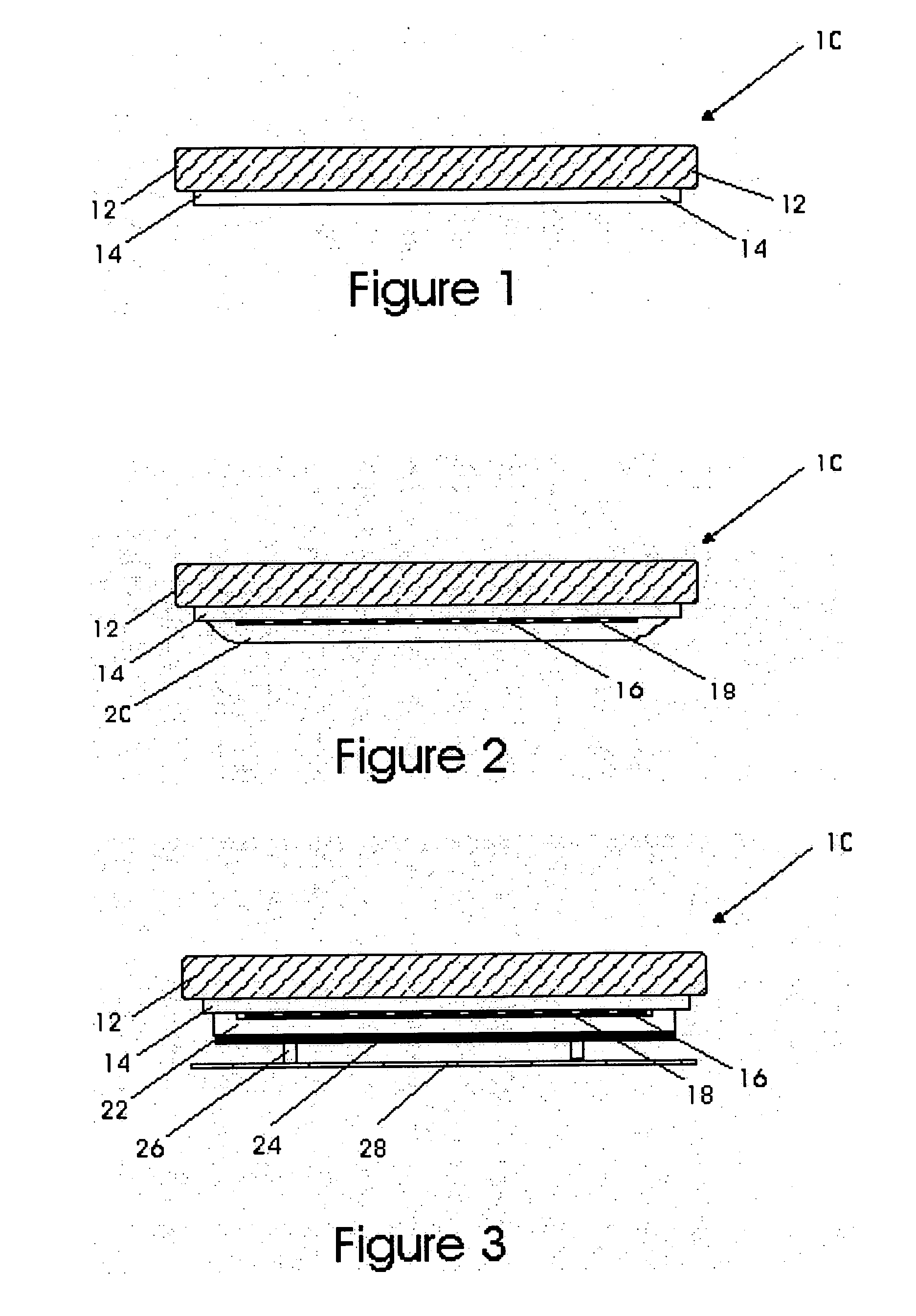
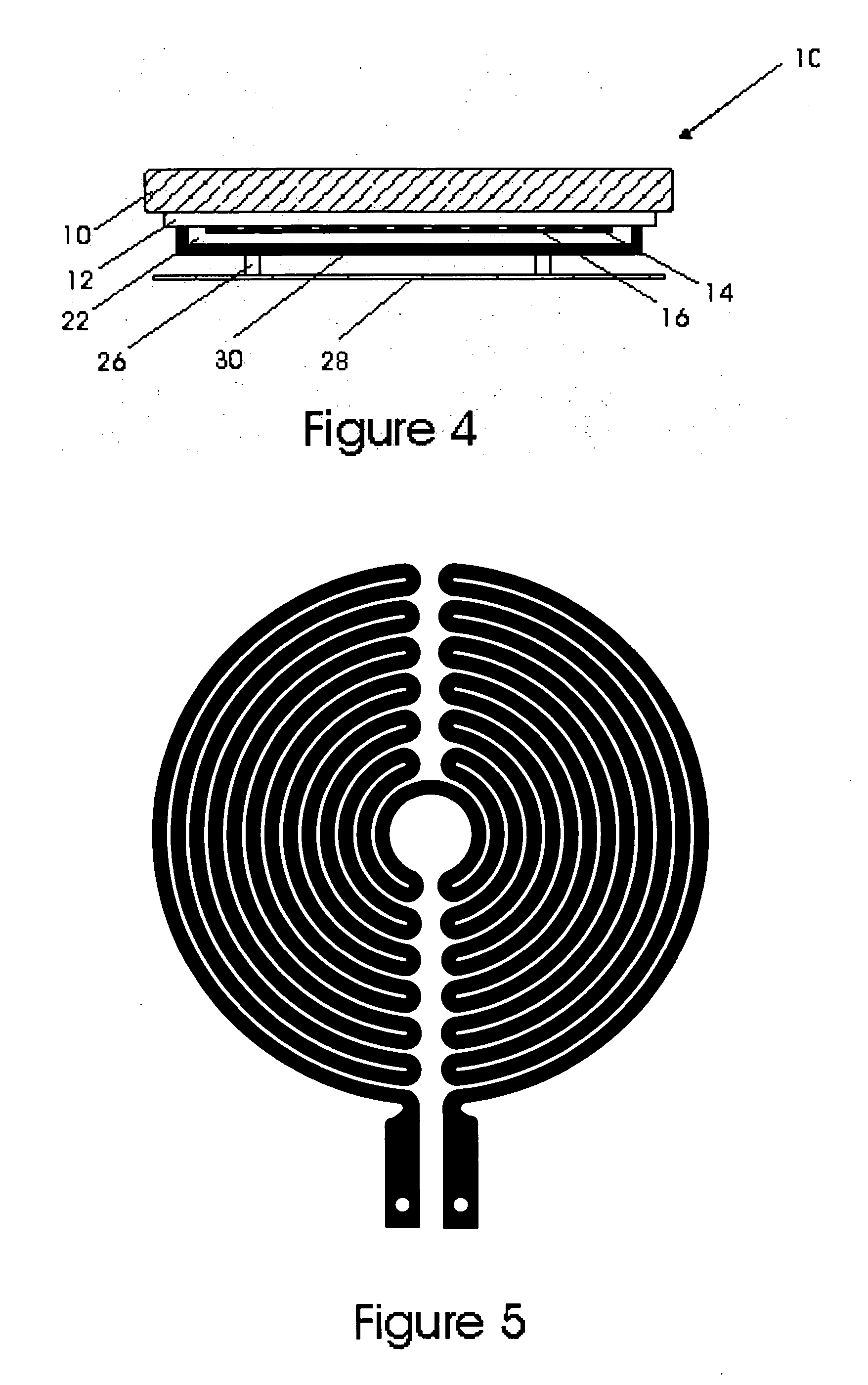
[0034] A high temperature glass ceramic cooktop such as shown at 10 in FIG. 2 was fabricated by forming the electrically insulating layer 14 on base substrate 12 by depositing 500 micrometers of sol gel composite alumina-silica, to form layer 14, onto zero expansion lithium aluminosilicate (LAS) glass ceramic base 12 as shown in FIG. 1. An etched foil resistive heating element 16 (FIG. 2) was made by attaching a 25 micrometer thick sheet of 304 stainless steel to 75 micrometers thick Firox™ mica paper backing material 18, using a silicone adhesive. Using a stainless steel etching solution, a meander pattern element with a circular envelope was produced as shown in FIG. 5. This etched foil 16 backed by mica paper 18 was placed on top of the dielectric coated 14 glass ceramic base 12 with the element 16 facing down so that it was in direct contact with the dielectric layer. The element 16 was then fixed in place using a high temperature aluminosilicate cement 20 as shown in FIG. 2. Th...

example 2

[0036] A high temperature glass cooktop was fabricated by depositing 500 micrometers of sol gel composite alumina / silica of sol gel composite alumina-silica onto zero expansion LAS glass ceramic. An etched foil was made by attaching a 25 micrometers thick sheet of 304 stainless steel to 75 micrometers thick Firox™ mica paper using a silicone adhesive. Using a stainless steel etching solution, a meander pattern element with a circular envelope was produced. This etched foil backed by mica paper was sandwiched between the dielectric coated glass ceramic, and a ¼ inch disk of lightweight, thermally insulating vermiculite board 22. The entire unit was then placed inside a fixture in which a pressure plate 24 backed by springs 26 connected to a mounting frame 28 were used to keep the vermiculite firmly affixed against the dielectric coated glass ceramic as shown in FIG. 3.

[0037] This unit passes the high pot standard for glass ceramic cook tops and operates stably up to element temperat...

example 3

[0038] A glass cooktop is made according to the design described in Example 2, except that the vermiculite disk is fixed to the dielectric coated glass ceramics by using silicone to attach the vermiculite around periphery of the disk, where the temperature is cooler.


PUM


Abstract

This invention relates to integrated heaters for use in a wide range of consumer and industrial applications. The integrated heater capable of high temperature operation includes a substrate that is coated with a suitable electrically insulating coating, a resistive heating element which may be a foil, ribbon or wire, placed on top of the electrically insulating coating, and a high temperature insulation material which is used to affix the heating element up against the coated substrate by sandwiching the heating element between the coated substrate and the insulating material and keep the heating element in close contact with the coated substrate. The insulating layer is able to provide both electrical insulation and efficient thermal transfer. This resulting integrated heating element is able to meet the regulatory electrical insulation requirements and is capable of operation in excess of 600° C. The element can also survive being repeatedly thermally cycled between room temperature and the specified operating temperature.

Description

CROSS REFERENCE TO RELATED U.S. APPLICATION [0001] This patent application relates to, and claims the priority benefit from, U.S. Provisional Patent Application Ser. No. 60 / 540,672 filed on Jan. 29, 2004, which is incorporated herein by reference in its entirety.FIELD OF THE INVENTION [0002] This invention relates to integrated heaters for use in a wide range of consumer and industrial applications. BACKGROUND OF THE INVENTION [0003] Integrated heaters, in which the heating element is directly attached or integrated with the material being heated, have long been sought after by the heating element industry. Many different approaches have been invented and developed over the years. [0004] One approach to making a low profile integrated heater is to use a thick resistive film that is attached to the material to be heated. One of the early thick film products is a silver / glass based formulation that has enabled the design of unique products such as fast boiling water kettles. However t...

Claims


Application Information

Patent Timeline
Patent Type & Authority Applications(United States)
IPC IPC(8): H05B3/26H05B3/68H05B3/74
CPCH05B3/262H05B3/265H05B3/748H05B3/74H05B3/68
Inventor OLDING, TIMKALLGREN, LARS JOHANRUGGIERO, MARY
Owner OLDING TIM
Learn More