Eureka AIR delivers breakthrough ideas for toughest innovation challenges, trusted by R&D personnel around the world.

Vehicle automatic emergency response system

a technology of automatic emergency response and vehicle, which is applied in the direction of traffic control system, alarm, electric signalling details, etc., can solve the problems of system, inability to be used inability to provide coverage in remote areas or areas where the mobile phone network has minimal coverage,

Inactive Publication Date: 2005-09-15
AUSTRALIAN ARROW
View PDF15 Cites 50 Cited by
  • Summary
  • Abstract
  • Description
  • Claims
  • Application Information

AI Technical Summary

Benefits of technology

[0011] It is therefore desirable to provide an improved form of automatic emergency response system that alleviates disadvantages of previously proposed systems.
[0012] It is also desirable to provide a system that is economical and simple to manufacture and install in vehicles or in other applications.
[0013] It is also desirable to provide a vehicle automatic emergency response system which facilitates the identification of a predefined event and which incorporates means for facilitating physical location of a vehicle or the like.
[0016] Simultaneously, a periodic or continuous homing beacon signal is transmitted by a radio beacon to facilitate manual location of the transmitter. The radio beacon may also include GPS data, if known, or other coding that may assist in locating the vehicle either from the air or the ground. However, it is an important feature of the invention that the beacon transmission is carried out in a way as to maximise battery life of the battery used to power the radio beacon.
[0017] The system may be powered from either the battery of the vehicle in which the system is located or from its own self-contained battery. Preferably, the vehicle battery is used to provide the power for the transmitters unless or until that supply is severed or exhausted at which time the self-contained, in-built battery provides the necessary power. In the case that the system is using the in-built battery, transmissions of the alarm signal transmitter may be reduced or minimised.

Problems solved by technology

A deficiency of such a system is that it is impractical to provide coverage in remote areas or areas where the mobile phone network has minimal coverage.
Such a system, therefore, would be unable to be used in those areas which are relatively high accident areas and which are most in need of an appropriate emergency response system.
However, satellite telephones tend to be rather large, heavy, expensive and require a subscription with associated cost.
This system, however, requires that the user terminal has both transmit and receive capabilities thereby increasing the cost of the user terminal.
This adds a level of complication to the user terminal.
Still further, the mobile terminal may be out of range when sending an initiation signal and, particularly if more than one mobile terminal is used in a search and rescue mission, a failure to activate the beacon may result in confusion as to its actual location.
While the system is multi-functional, it is also very complicated, of relatively large size and expensive to produce.
Thus, in the event of a vehicle accident in which the vehicle battery is dislodged or disconnected or otherwise rendered inoperable, the system of this patent would be inoperative.

Method used


Image

  • Vehicle automatic emergency response system
  • Vehicle automatic emergency response system
  • Vehicle automatic emergency response system

Examples


Embodiment Construction

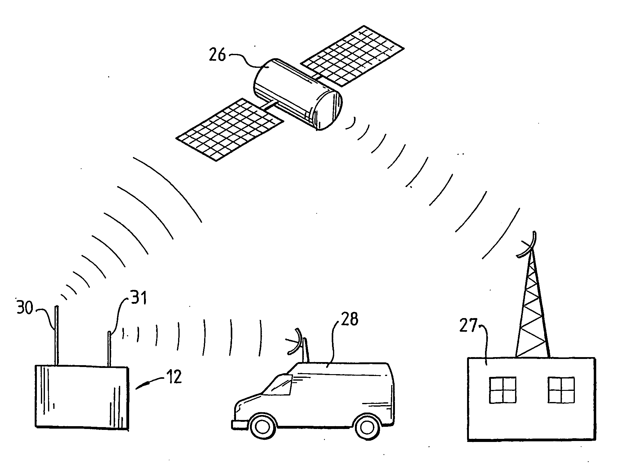
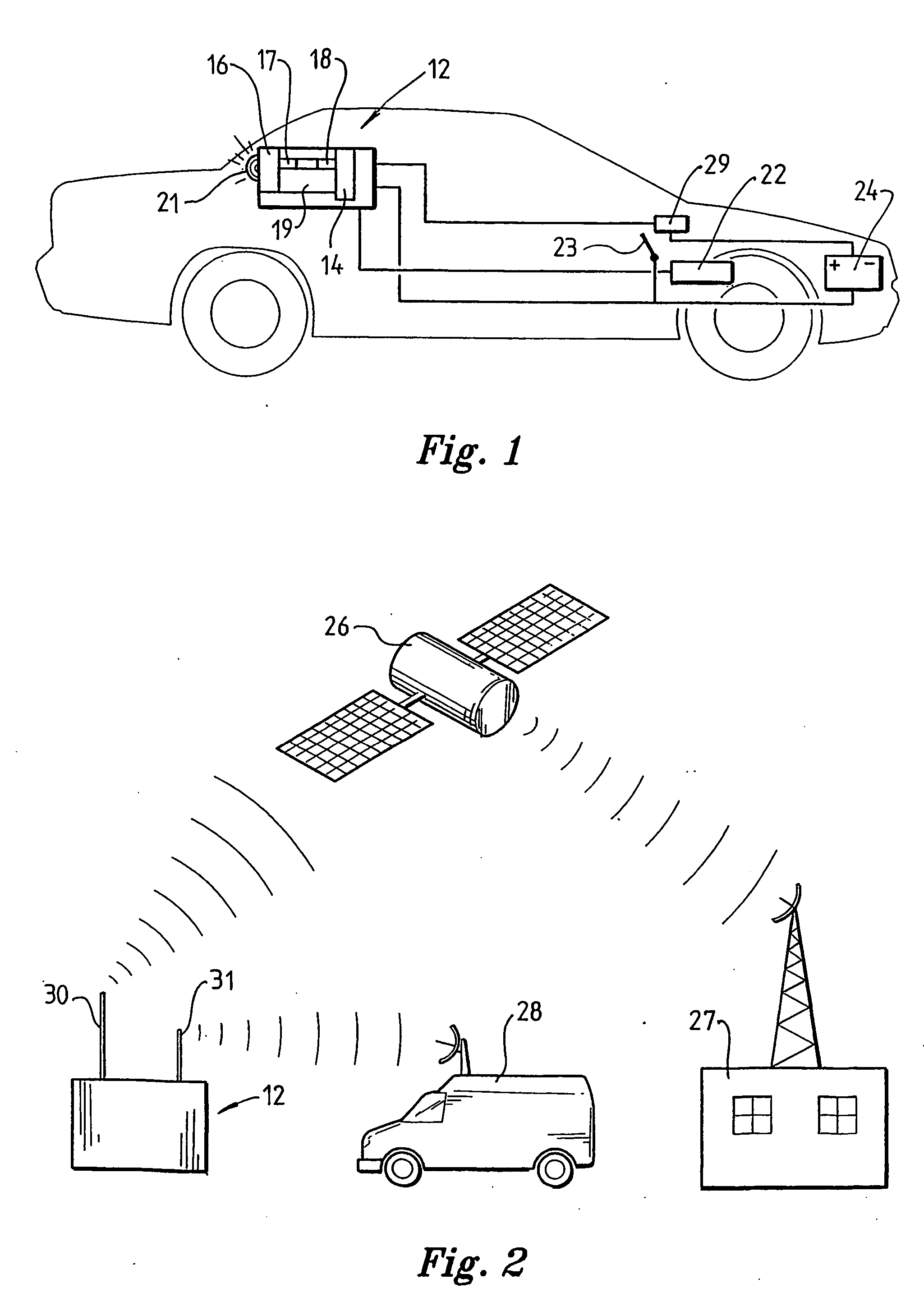
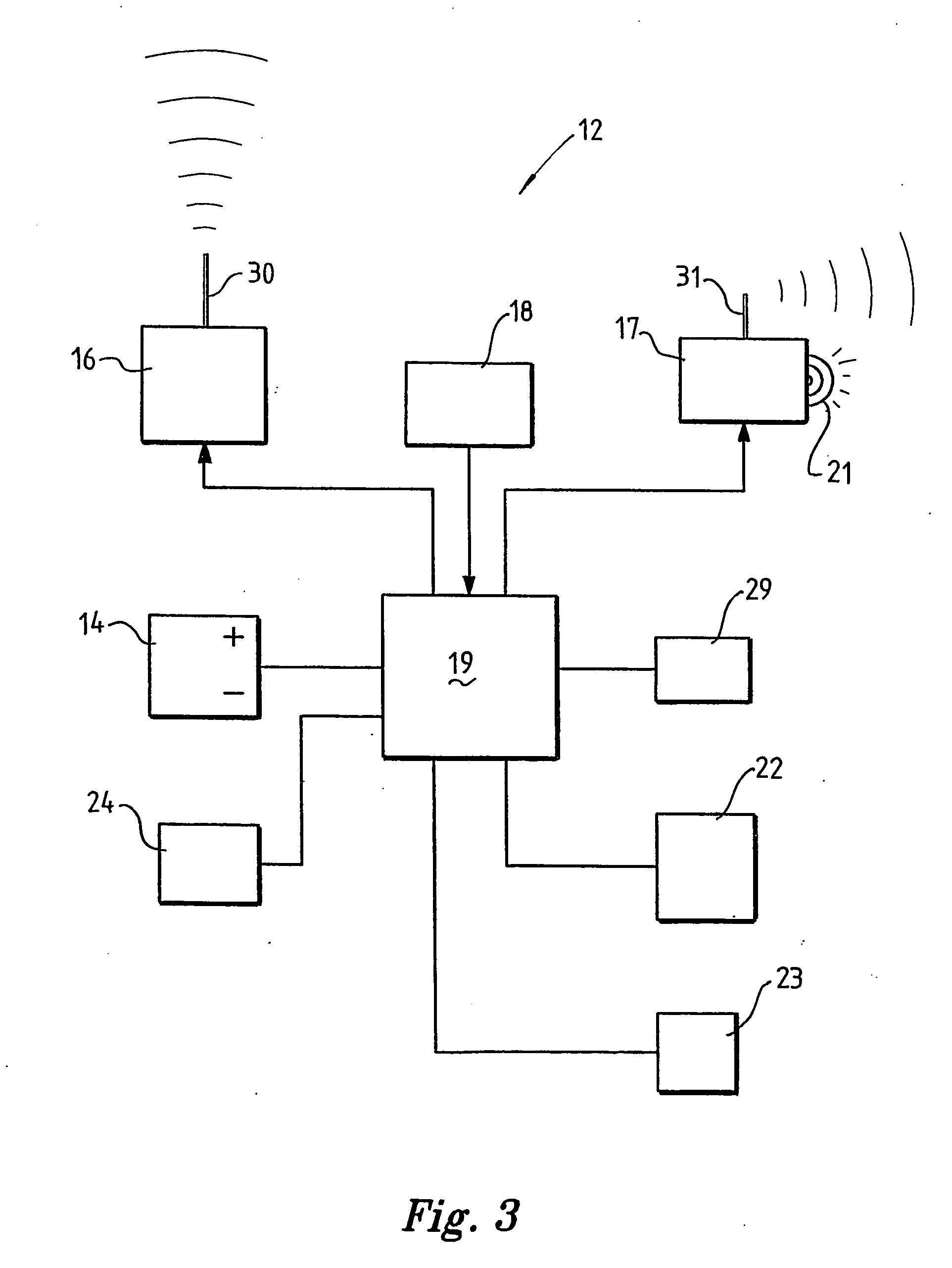
[0029] Referring to the drawings, FIGS. 1 to 3 schematic illustrate an embodiment of the invention installed in a motor vehicle. The system 12 is preferably mounted in a relatively protected area of the vehicle, such as beneath a rear parcel shelf or adjacent a forward crash pad. The system 12 incorporates the in-vehicle components shown more particularly in the block diagram of FIG. 3, and includes an in-built power supply battery 14, an alarm signal transmitter 16, a radio beacon transmitter 17, a GPS unit 18 and control circuitry 19. The system of this embodiment may also include a strobe lamp 21 for producing light pulses.

[0030] The vehicle in which the system is installed includes an accelerometer 22 which is used to initiate operation of the vehicle air bag system in response to an accident or impact. Although only one accelerometer 22 is illustrated, it will be understood that vehicles in which the system is installed may have any number of accelerometers for a plurality of ...


PUM


Abstract

An automatic emergency response system is operable to notify an emergency center of a defined event, such as a vehicle accident. The system facilitates location of the event, by using position determining means, such as GSP, to establish its at least approximate location. A control circuit includes code generating means to generate a coded signal incorporating the position location information. An alarm signal transmitter is operable on occurrence of the defined event to transmit an alarm signal incorporating the coded signal to a receiving station, which may be a satellite, which relays the message to the emergency center, including the positional information relating to the location of the transmitter. A relative low power homing signal transmitter simultaneously transmits a homing signal either continuously or at periodic intervals.

Description

FIELD OF THE INVENTION [0001] This invention relates to a vehicle automatic emergency response system and relates particularly to such a system able to be used to identify and locate a vehicle on the occurrence of a defined event, such as an accident involving that vehicle. [0002] Although the invention will be described with particular reference to its use in relation to motor vehicles, it will be apparent that the invention has application to boats and even aircraft, hang gliders, ultra-light aircraft vehicles and the like. BACKGROUND OF THE INVENTION [0003] Forms of vehicle emergency response systems have been previously proposed. In one proposal, an emergency response system requires the use of a mobile phone network in conjunction with GPS or possibly mobile phone network cell based positioning. A deficiency of such a system is that it is impractical to provide coverage in remote areas or areas where the mobile phone network has minimal coverage. Such a system, therefore, would...

Claims


Application Information

Patent Timeline
IPC IPC(8): B60Q1/52B60Q9/00B60R21/00B60R21/16B60R22/46B62D41/00G01S19/48G08B25/10G08G1/123G08G1/127
CPCB60Q1/52G08G1/205B62D41/00
Inventor JAMES, CAMPBELL RICHARD
Owner AUSTRALIAN ARROW
Why Eureka
Eureka Blog
Learn More