
Methods for remote monitoring and control of appliances over a computer network

a technology of computer network and remote monitoring, applied in the field of data transmission over a network, can solve the problems of bandwidth requirements, difficult operation of wedcams, and expensive conventional approach to remote monitoring, and achieve the effects of facilitating remote monitoring and control, efficient transmission of images, and facilitating efficiency

Inactive Publication Date: 2005-09-08
ATC ADVANCED TECH CO LLC
View PDF69 Cites 192 Cited by
  • Summary
  • Abstract
  • Description
  • Claims
  • Application Information

AI Technical Summary

Benefits of technology

[0011] The remote monitoring of locations is provided by efficiently transmitting images over the network to a remote machine located at a remote location. In one embodiment, the efficiency is facilitated by comparing a current image with a reference image, and then only transmitting the current image if it differs from the reference image by more than a predetermined threshold amount. The remote monitoring can also operate as an alarm system or provide intruder detection based on detected changes in images from a locally provided camera.

Problems solved by technology

This conventional approach to remote monitoring is expensive to implement because specialized equipment and personnel are required.
However, the operation of these WedCams is problematic because of the high bandwidth requirements to transmit video from the camera serving as the WebCam and its server and viewers.
Again, however, to limit bandwidth requirements, the Internet browser only periodically accesses (or receives by a push from) the Internet server to retrieve the newest images after a predetermined period of time.
Although this conventional approach does limit the bandwidth utilization, the amount of bandwidth being utilized is nevertheless largely wasted when the image is not significantly changing.

Method used


Image

  • Methods for remote monitoring and control of appliances over a computer network
  • Methods for remote monitoring and control of appliances over a computer network
  • Methods for remote monitoring and control of appliances over a computer network

Examples


Embodiment Construction

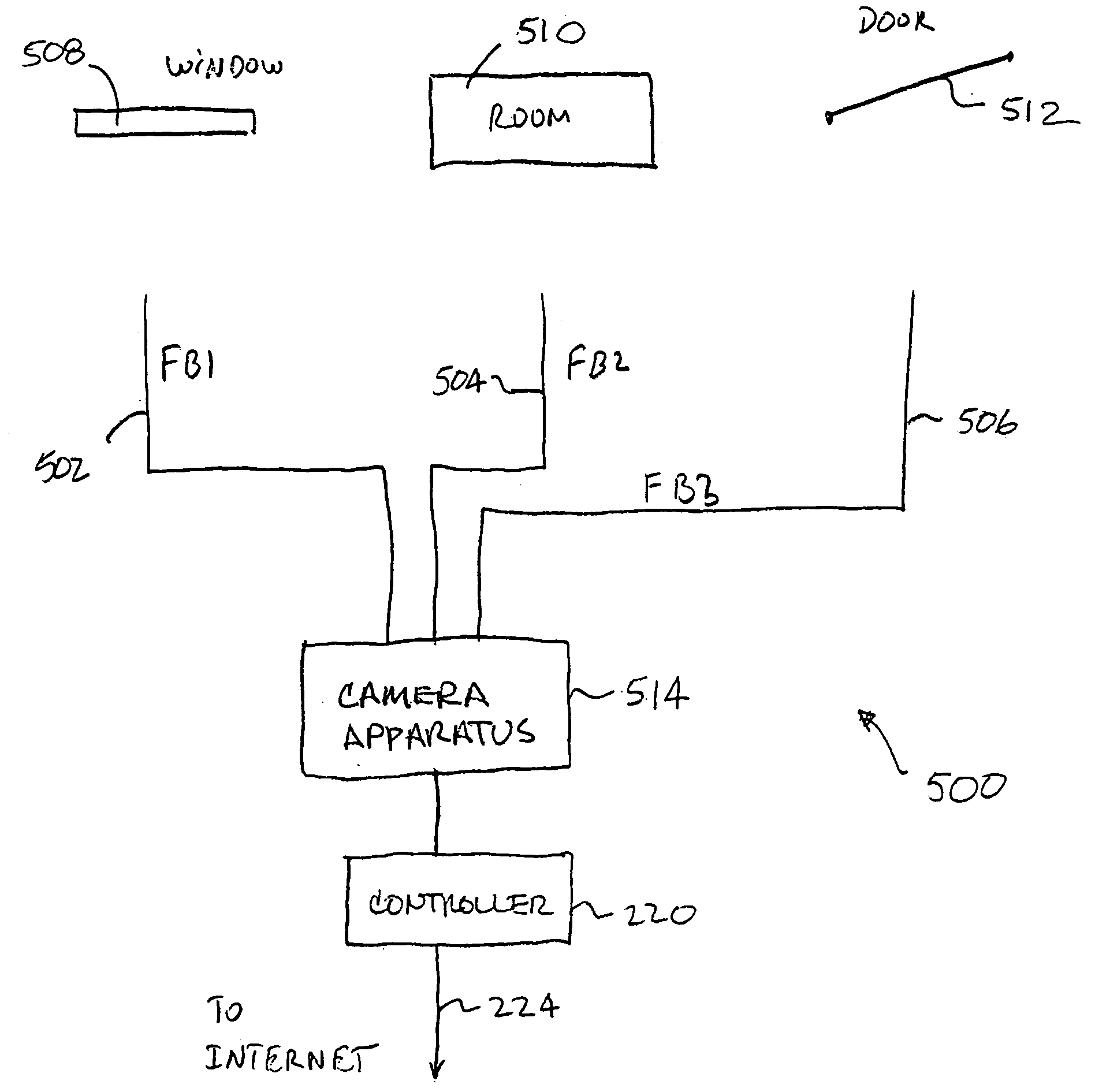
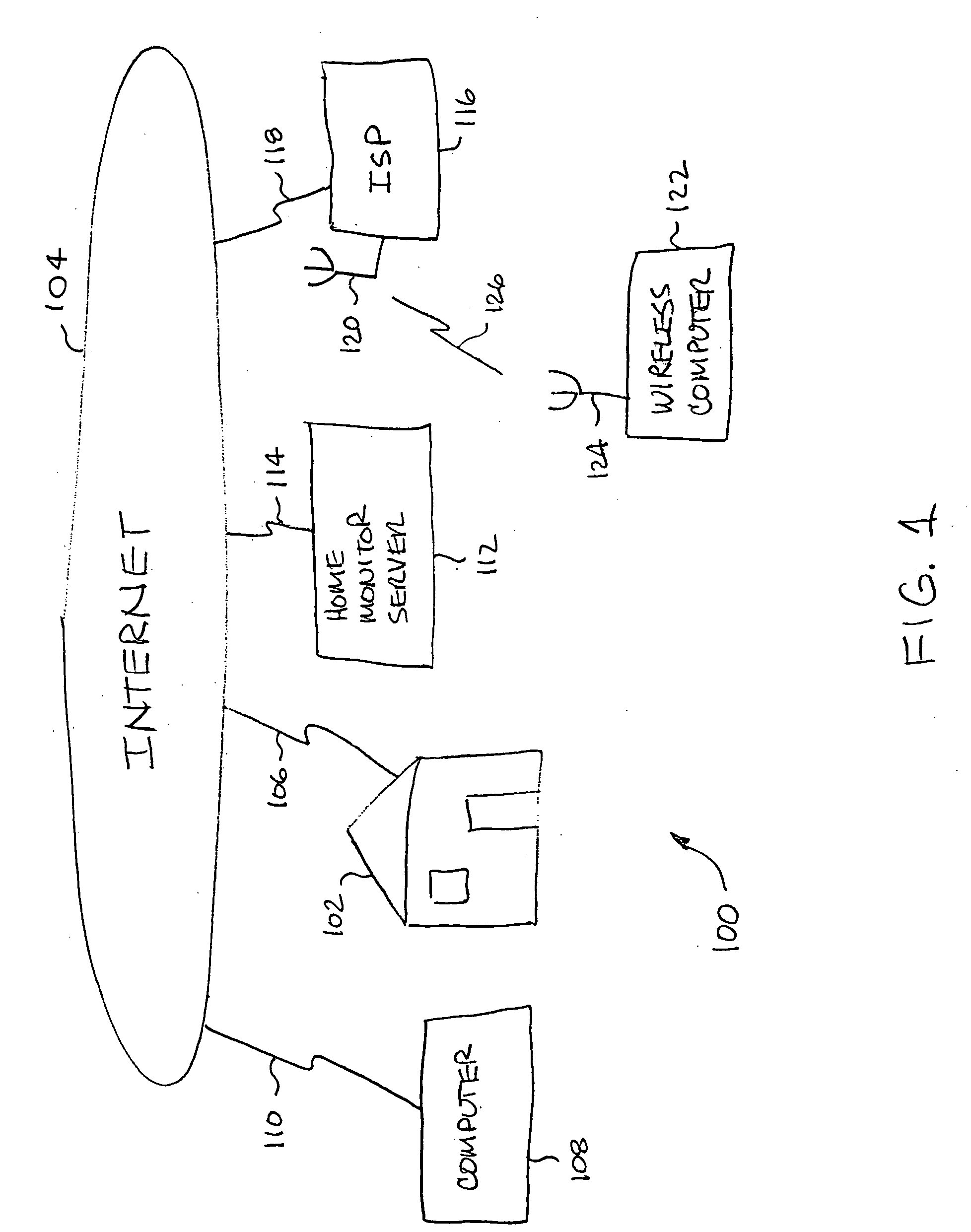
[0042] The invention relates to improved techniques to remotely monitor locations, to detect activity, and to remotely monitor and control devices or appliances through a network. In one embodiment, the network is the Internet and the transmission is facilitated by an Internet server or electronic mail.

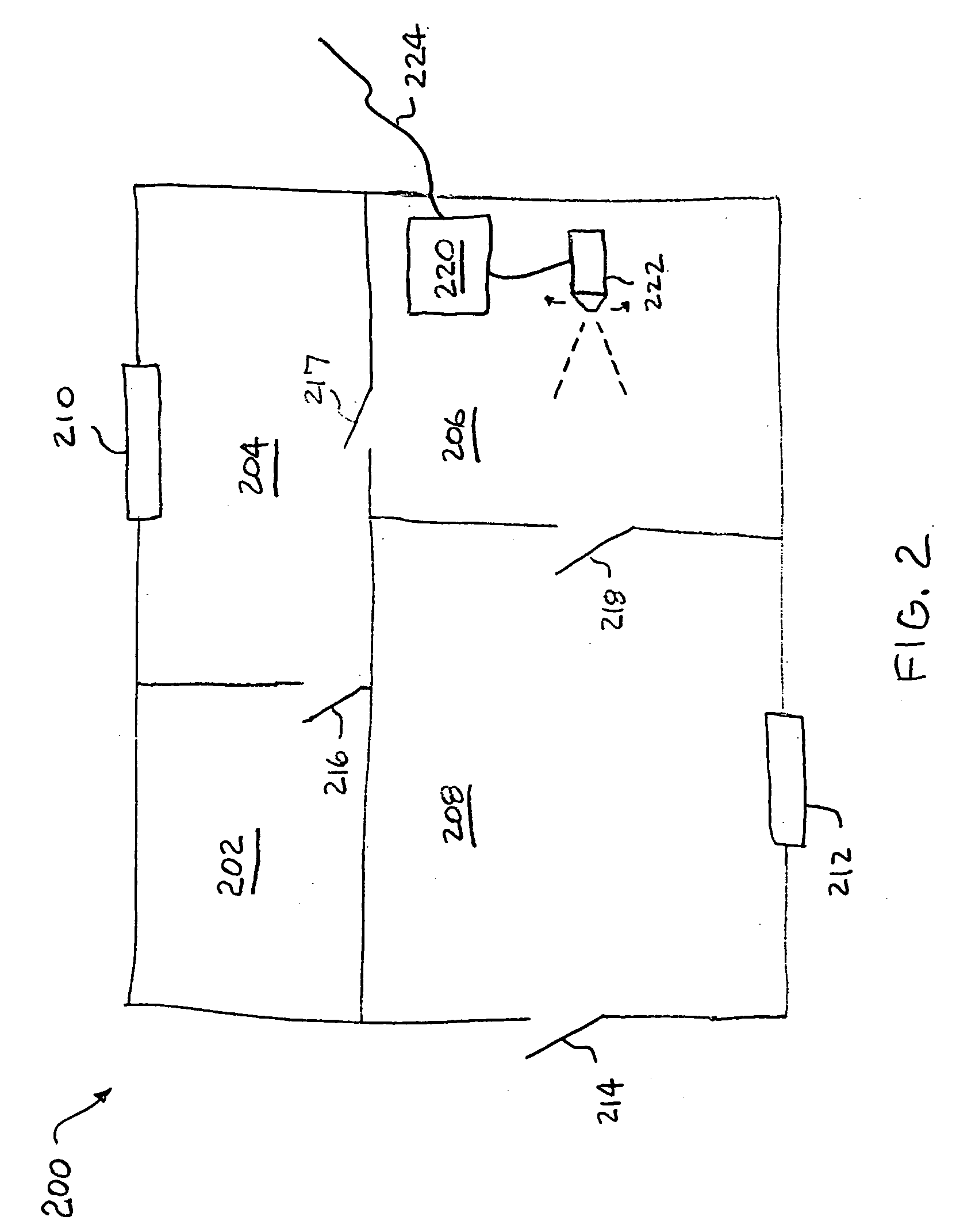
[0043] The remote monitoring of locations is provided by efficiently transmitting images over the network to a remote machine located at a remote location. In one embodiment, the efficiency is facilitated by comparing a current image with a reference image, and then only transmitting the current image if it differs from the reference image by more than a predetermined threshold amount. The remote monitoring can also operate as an alarm system or provide intruder detection based on detected changes in images from a locally provided camera.

[0044] The remote monitoring and controlling of controllable devices is provided by sending control information to and receiving status information...


PUM


Abstract

The remote monitoring and controlling of controllable devices is provided by sending control information to and receiving status information from information appliances over a network. A user is able to monitor the information appliances from a remote location, and control the information appliances from the remote location. The remote monitoring and control can be facilitated by graphical user interfaces. The information appliance can be a home lighting system, a home alarm system, a home entertainment system, a water gardening system, a home heating system, a home cooling system, and a television system having recording capabilities.

Description

CROSS REFERENCE TO RELATED APPLICATION [0001] This application is a divisional application and claims 35 U.S.C. §120 priority from U.S. patent application Ser. No. 09 / 098,279, filed Jun. 16, 1998 and entitled “METHOD AND APPARATUS FOR REMOTE MONITORING AND CONTROL OVER A COMPUTER NETWORK” and such application claims benefit of priority under 35 U.S.C. 119(e) of U.S. Provisional Application No. 60 / 051,489, filed Jul. 1, 1997 and entitled “METHOD AND APPARATUS FOR REMOTE MONITORING AND CONTROL OVER A COMPUTER NETWORK”, the contents of each application is hereby incorporated by reference.BACKGROUND OF THE INVENTION [0002] 1. Field of the Invention [0003] The present invention relates to data transmissions over a network, and more particularly, to remote monitoring and control of articles over a network. [0004] 2. Description of the Related Art [0005] Remote monitoring of buildings or grounds is often done for security reasons. One conventional approach to remote monitoring of buildings...

Claims


Application Information

Patent Timeline
IPC IPC(8): G06F17/00
CPCG05B15/02G05B2219/2642H04L51/02H04L67/125H04L12/2818G08B25/08H04L67/55
Inventor THOMAS, C. DOUGLASSPENILLA, ALBERT S.NGUYEN, JOSEPH A.
Owner ATC ADVANCED TECH CO LLC
Learn More