
Cotdr arrangement with swept frequency pulse generator for an optical transmission system

a technology of optical transmission system and swept frequency pulse, which is applied in the direction of transmission monitoring, transmission monitoring/testing/fault-measurement system, electrical apparatus, etc., can solve the problems of cotdr signal loss, cotdr signal loss, and cotdr signal loss, so as to reduce the effect of fwm

Active Publication Date: 2005-09-08
HUAWEI MARINE NETWORKS CO LTD
View PDF22 Cites 53 Cited by
  • Summary
  • Abstract
  • Description
  • Claims
  • Application Information

AI Technical Summary

Benefits of technology

[0016] In accordance with another aspect of the invention, the traffic signals are located at one or more wavelengths sufficiently remote from a waveband occupied by the cw probe signal to reduce FWM and XPM so that both the quality of the optical traffic signals and COTDR sensitivity are maintained at acceptable levels.

Problems solved by technology

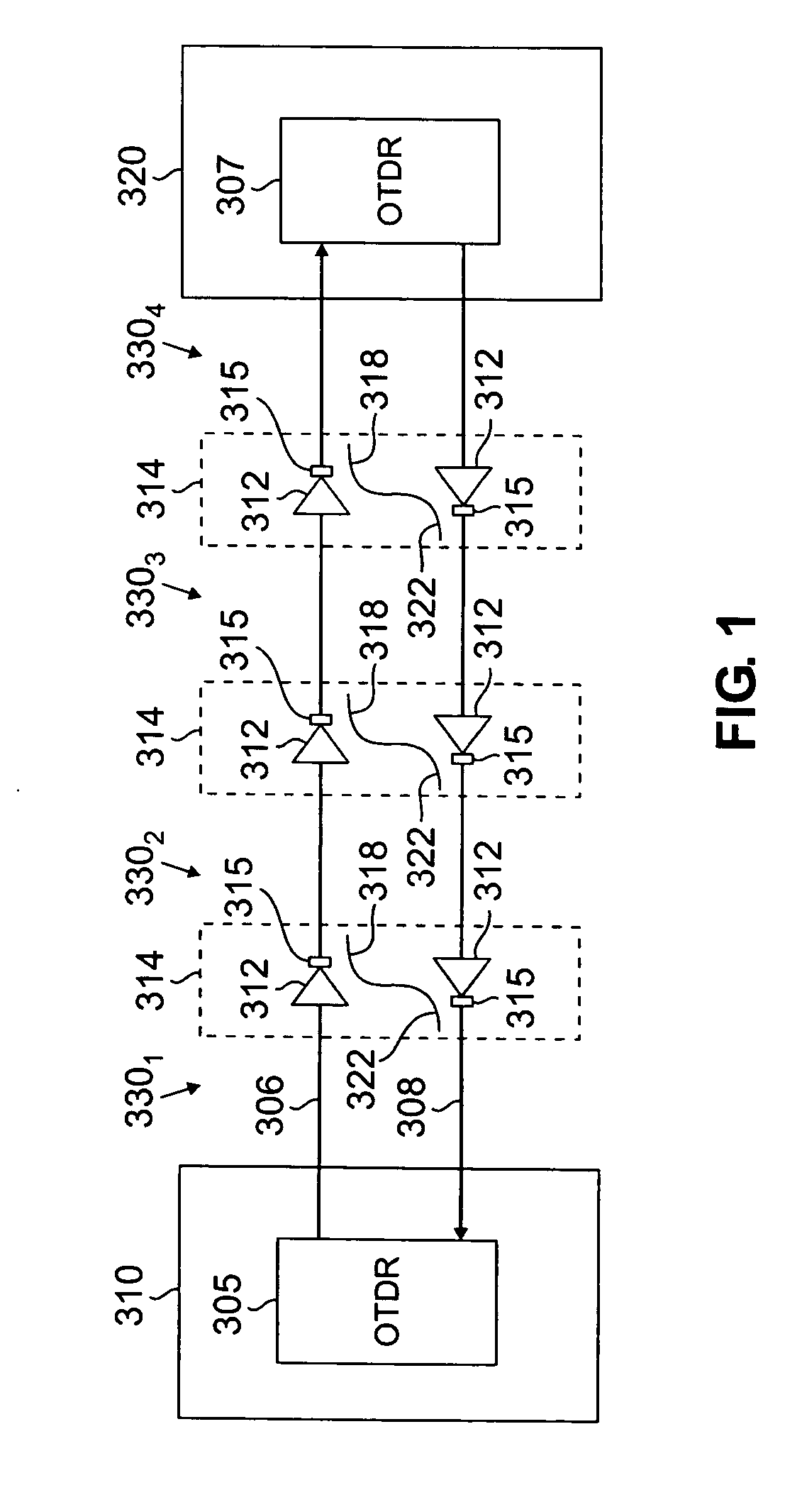
One complication that occurs when COTDR is used in a multi-span transmission line in which the individual spans are concatenated by repeaters is that the optical isolators located downstream from each repeater prevent the backscattered signal from being returned along the same fiber on which the optical pulse is initially launched.
The previously mentioned two features of the COTDR pulse, high power and low duty cycle, generally make COTDR unacceptable for use when the transmission system is in-service (i.e., when it is carrying customer traffic).
Since the COTDR receiver has quite a narrow bandwidth, some of the power in the COTDR signal will be lost as it traverses the receiver, thereby lowering its optical signal-to-noise-ratio (OSNR) and significantly impairing the COTDR sensitivity.
Another reason why it is problematic to use COTDR in-service is because the COTDR pulses give rise to gain fluctuations that cause transient behavior in the optical amplifiers.
However, when such a gain change occurs at every optical amplifier along the transmission path, the cumulative effect becomes problematic.
The signal degradation that results generally will be unacceptable for a system that does not build in extra margin specifically for this type of degradation.

Method used


Image

  • Cotdr arrangement with swept frequency pulse generator for an optical transmission system
  • Cotdr arrangement with swept frequency pulse generator for an optical transmission system
  • Cotdr arrangement with swept frequency pulse generator for an optical transmission system

Examples


Embodiment Construction

[0028] The present invention overcomes the aforementioned problems and limitations of conventional COTDR arrangements that arise from gain fluctuations associated with the long duty cycle of the COTDR probe pulses. Instead of a pulse generator that launches long duty cycle probe pulses, the present invention employs a CW laser having an output frequency that is swept over an appropriate range. As explained in more detail below, the COTDR receiver has a fixed frequency local oscillator that is sensitive to a single frequency swept by the CW laser.

[0029] One important advantage of the present invention is that because the COTDR arrangement employs a cw laser instead of a pulsed source, the optical power level “seen” by the optical amplifiers will remain constant in time when the COTDR arrangement is in use. Accordingly, gain fluctuations and the associated signal degradations due to cross gain coupling will not arise, thereby allowing the COTDR arrangement to be used when the transmi...


PUM


Abstract

A method and apparatus is provided for obtaining status information from a given location along an optical transmission path. The method begins by generating a cw probe signal having a prescribed frequency that is swept over a prescribed frequency range. The cw probe signal is transmitted over the optical path and a returned COTDR signal in which status information concerning the optical path is embodied is received over the optical path. A receiving frequency within the prescribed frequency range of the returned COTDR signal is detected to obtain the status information. The detecting step includes the step of sweeping the receiving frequency at a rate equal to that of the prescribed frequency. A period associated with the receiving frequency is temporally offset from a period associated with the prescribed frequency.

Description

RELATED APPLICATIONS [0001] This application is related to U.S. appl. Ser. No. ______ [Red Sky Docket No. 32] entitled “Method and Apparatus for Obtaining Status Information Concerning An In-Service Optical Transmission System,” filed on even date herewith. FIELD OF THE INVENTION [0002] The present invention relates generally to optical transmission systems, and more particularly to the use of an arrangement to allow coherent optical time domain reflectometry (COTDR) to be used to detect faults in the optical transmission path of an optical transmission system consisting of multiple spans of fiber and optical amplifiers. BACKGROUND OF THE INVENTION [0003] A typical long-range optical transmission system includes a pair of unidirectional optical fibers that support optical signals traveling in opposite directions. An optical signal is attenuated over long distances. Therefore, the optical transmission line will typically include repeaters that restore the signal power lost due to fib...

Claims


Application Information

Patent Timeline
IPC IPC(8): H04B10/00
CPCH04B10/0771
Inventor EVANGELIDES, STEPHEN G. JR.NAGEL, JONATHAN A.
Owner HUAWEI MARINE NETWORKS CO LTD
Learn More