
Electrically conductive coatings with high thermal oxidative stability and low thermal conduction

Inactive Publication Date: 2005-09-01
EIKOS
View PDF6 Cites 43 Cited by
  • Summary
  • Abstract
  • Description
  • Claims
  • Application Information

AI Technical Summary

Benefits of technology

[0017] The present invention overcomes the problems and disadvantages associated with current strategies and designs and provides new tools and methods

Problems solved by technology

Currently resistive films that are used on aeronautical and space platforms in high temperature environments have low durability and are costly to repair and maintain.
Protective coatings that provide electrical conductivity in environments with high temperatures, high vibration characteristics, moisture, solvents, fuels and oxygen, typically have short useful lifetimes. The degradation of electrical properties after exposure to such environments reduces the primary function of the coating making repair or replacement necessary.
The degradation of electrical properties can be attributed to failure of the binder or the conductive fillers.
If either primary component fails the properties of the composite coating / film will degrade.
Metal are subject to oxidation, corrosion and reaction with environmental compounds aggravated at elevated temperatures.
Furthermore, degradation of the coating properties can come about through failure of the filler.
However even if the polymer has a very high thermal oxidative stability, the filler may prove to be the weak link in the composite, such that the filler oxidizes, slough's off the surface, or reacts with other compounds in the environments.
All of this will cause the coating's electrical and other properties to diminish.
Even if the polymer where replaced with a high temperature material like a ceramic, the filler will still fail.

Method used


Image

  • Electrically conductive coatings with high thermal oxidative stability and low thermal conduction
  • Electrically conductive coatings with high thermal oxidative stability and low thermal conduction
  • Electrically conductive coatings with high thermal oxidative stability and low thermal conduction

Examples


example 1

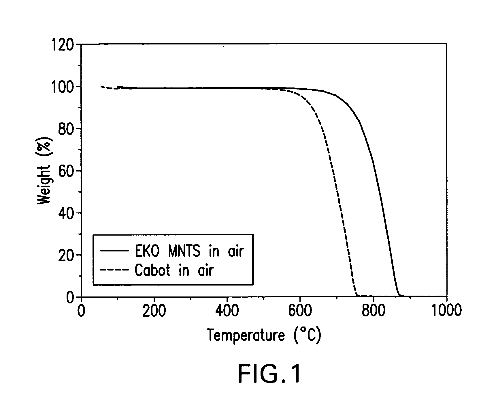
[0047] Thermal Oxidative Stability (TOS) was evaluated for carbon black, carbon nanotubes and carbon nanofibers. Two plots were generated: 1) short term TGA and 2) Long-term TGA ˜100 hours at 700° F., collected on both high electrical conductivity carbon black (Cabot Corporation) and purified multiwalled carbon nanotubes (see FIG. 1). From this data it is clear that the onset temperature of degradation is higher for the carbon tubes than for the carbon black (CB). Also, there were very low (<0.3%) residual weight on the nanotubes, indicating very low noncombustible contaminates like metals. EKO MNTS are multiwalled carbon nanotubes (Electrovac GesmbH, Austria).

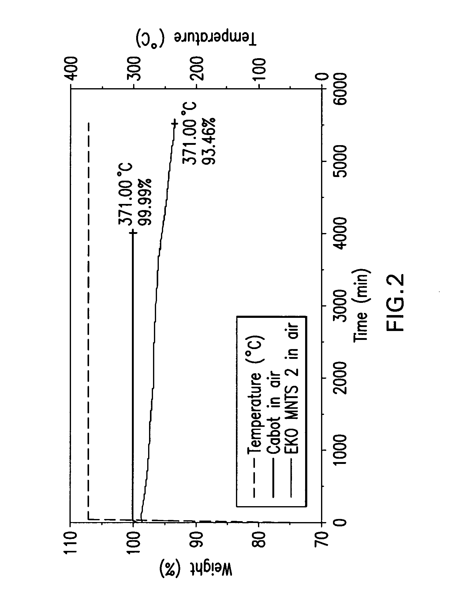
[0048] The long-term testing shows gradual weight loss for the CB throughout the 100 hours period of the test with total loss of ˜5.5% Wt. However for the nanotubes, zero weight loss was recorded after 70 hours at 700° F. No change in weight after 70 hours at 700° F. Subsequent testing at 850° F. showed the same result. Test ...

example 2

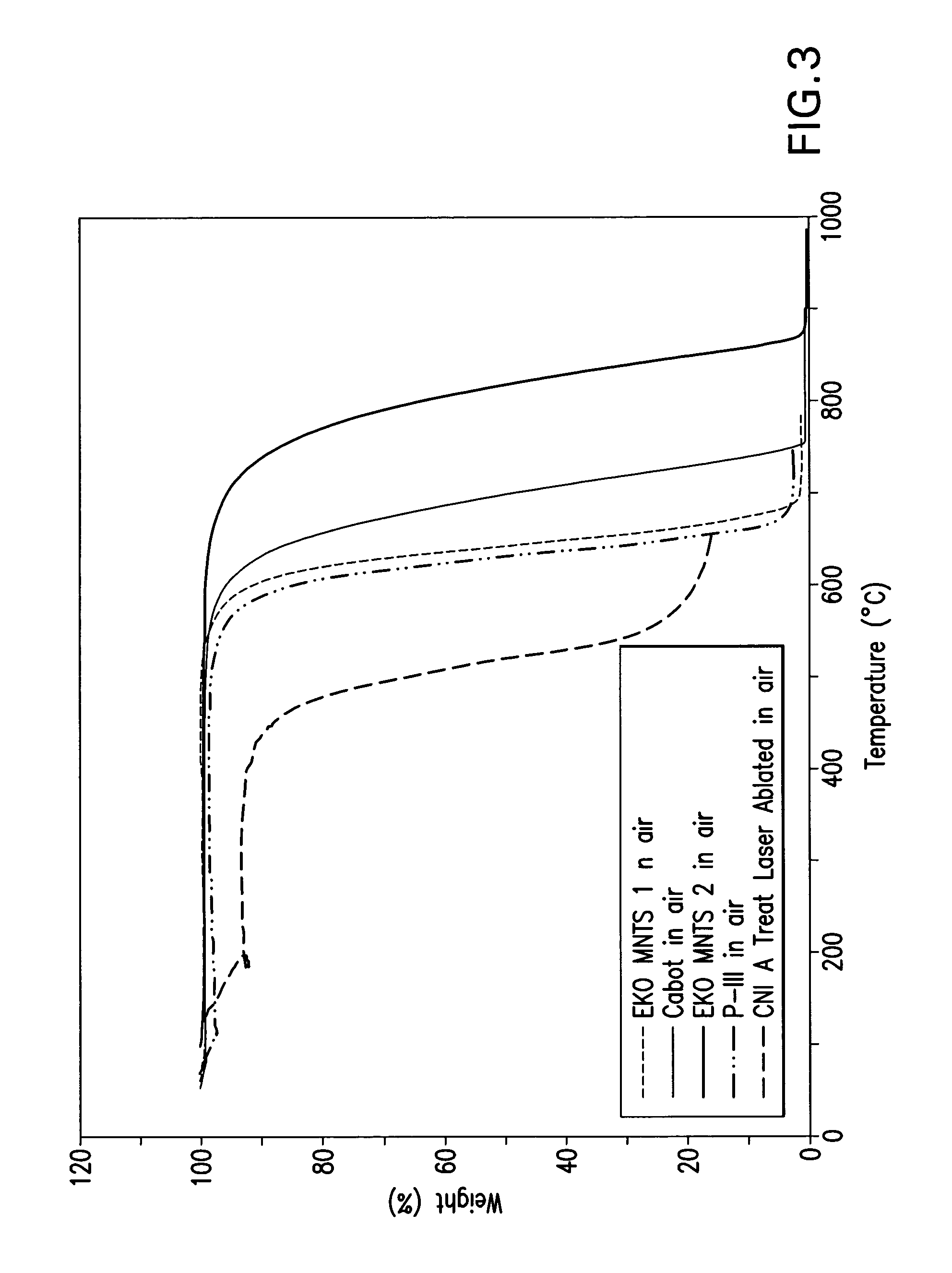
[0052] Additional Thermal Oxidative Stability (TOS) evaluations were performed for different form of carbon for use in conductive coatings. The ramp data of FIG. 3 indicates two factors of interest when evaluating the TOS of neat carbon in air. CNI A are single walled carbon nanotubes (CNI, Inc., Houston, Tex.). The first is the onset of degradation and the second is the residual weight after complete decomposition. Note that the residual weight seems related to the onset temperature; which could be due to metal content. Short term TGA data were collected using conditions where the sample is ramped till failure, and correlates to the long term TGA test performed at isothermal hold.

[0053] Essentially, the higher the on-set temperature during ramp to failure, the lower the weight loss during isothermal hold. Additionally, the lower the residual weight after full decomposing the higher the onset temperature. These patterns could be misleading should be environment or other conditions ...

example 3

Electrical Properties

[0055] Electrical properties as a function of temperature were determined for carbon tube filled urethane and ceramic coatings. Urethane polymers provided the best near-term solution for a well dispersed filled system for coating and optical testing. The castable ceramic (Al2O3) allowed exploration of the high temperature behavior of dilute carbon tube fillers. For simplicity, only data for 0.5% loading of nanotubes in the various matrices is presented in FIG. 4. Higher loading of NTs were tested.

[0056] Electrical resistance for an ESD coating should be between 106 to 1010 ohm per square for most space applications. Additionally the ESD coating should maintain electrical conductivity throughout the operational temperature range experienced in space. Typically, satellites experience wide temperature cycles due to solar radiation combined with the varying flux density of charged particles. On spacecraft with outward-facing dielectric materials (which most are), ...


PUM

PropertyMeasurementUnit
Fractionaaaaaaaaaa
Fractionaaaaaaaaaa
Fractionaaaaaaaaaa

Abstract

The present invention is directed to electrically conductive coatings of carbon that have high thermal oxidative stability and low thermal conduction. Coatings of the invention provide a surface resistivity to the coated substrate of 102 ohms / square, and preferably 10−2 ohms / square. Coatings also provide the coated article increased thermal oxidative stability as compared to the uncoated article and articles coated with convention materials like carbon black and metals, as well as low thermal conduction. The invention is also directed to substrates possessing conductive coatings, methods of utilizing the coated substrates, and to methods of forming the coatings of the invention.

Description

REFERENCE TO RELATED APPLICATIONS [0001] This application claims priority to U.S. Provisional Application No. 60 / 515,419 entitled “Electrically Conductive Coatings with High Thermal Oxidative Stability and Low Thermal Conduction” filed Oct. 30, 2003, the entirety of which is hereby incorporated by reference.RIGHTS IN THE INVENTION [0002] This invention was made, in part, with support from the United States government under a grant from the United States National Aeronautics and Space Administration, Contract No. NAS 1-02116. Accordingly, the United States government may have certain rights in the invention.BACKGROUND [0003] 1. Field of the Invention [0004] The present invention is directed to electrically conductive coatings of carbon that have high thermal oxidative stability and low thermal conduction. The invention is also directed to substrates possessing such conductive coatings, methods of utilizing the coated substrates, and to methods of forming the coatings. [0005] 2. Descr...

Claims


Application Information

Patent Timeline
IPC IPC(8): B05D1/36B32B9/00C09D7/61H01L51/00
CPCB82Y10/00B82Y30/00C08K3/04C09D5/24Y10T428/30H01B1/18H01B1/24H01L51/0048C09D7/1291C09D163/00C09D175/04C09D179/08C08K3/041C08K3/046C09D7/70C09D7/61H10K85/221
Inventor GLATKOWSKI, PAUL J.
Owner EIKOS
Learn More