
Steel piston ring

a technology of steel piston ring and chromium plating layer, which is applied in the direction of brake systems, machines/engines, transportation and packaging, etc., can solve the problems of increasing the requirements of piston ring, and increasing the cost of piston ring

Inactive Publication Date: 2005-08-25
RIKEN CO LTD
View PDF9 Cites 19 Cited by
  • Summary
  • Abstract
  • Description
  • Claims
  • Application Information

AI Technical Summary

Benefits of technology

[0024] It is needless to say that, from a technical aspect, it is possible to provide versatile combinations of piston rings including pressure rings having an straight face which satisfy the constitutional features of the present invention in at least two or all pressure rings among a plurality of pressure rings.

Problems solved by technology

The first pressure ring is positioned close to the combustion chamber and hence, the first pressure ring is subjected to high temperature and not sufficiently lubricated.
Recently, however, along with the increase of demand for higher speed, higher output and lower fuel consumption with respect to an internal combustion engine, requirements for piston ring are getting severer year by year.
Under such circumstances, with respect to the first pressure ring, the conventional cast-iron piston ring having the chromium plating layer is not sufficient in view of the strength and the wear resistance.
However, the machinability of the steel material is inferior to that of the cast iron material.
However, as mentioned previously, since the steel material is tough, it is difficult to remove swarf or turnings from the piston ring thus increasing the generation of so-called “burrs”.
Accordingly, compared with the use of the cast-iron material, to suppress the generation of the burrs, it is necessary to provide means such as reducing a grinding speed, making a depth of cut small and the like thus remarkably decreasing the machining productivity.
When this known technique is applied to a steel piston ring, as mentioned previously, problems still remain with respect to the suppression of the generation of burrs and the machining productivity.
Further, to mention performances of the piston ring, it is necessary to provide additional shapes to the piston ring and hence, following problems arise.

Method used


Image

  • Steel piston ring
  • Steel piston ring
  • Steel piston ring

Examples


embodiments

[0048] As a first pressure ring of a gasoline engine, a steel barrel-face ring (see FIG. 5 and FIG. 6) and a taper-face ring (see FIG. 7 and FIG. 8) having a nominal outer diameter of φ75×a width of 1.2 mm×a thickness of 2.3 mm are produced.

[0049] As a second pressure ring of the gasoline engine, a steel taper-face ring (see FIG. 7 and FIG. 8) having a nominal outer diameter of φ75×a width of 1.5 mm×a thickness of 2.6 mm is produced.

[0050] As a first pressure ring of a diesel engine, a steel barrel-face ring (see FIG. 5 and FIG. 6) having a nominal outer diameter of φD99.2×a width of 2.5 mm×a thickness of 3.9 mm is produced.

[0051] As a second pressure ring of the diesel engine, a steel taper-face ring (see FIG. 7 and FIG. 8) having a nominal outer diameter of φ99.2×a width of 2.0 mm×a thickness of 4.1 mm is produced.

[0052] These steel piston rings are served for engine tests to confirm the advantageous effects of the present invention (see FIG. 9 to FIG. 11).

[0053] A wire mater...


PUM


Abstract

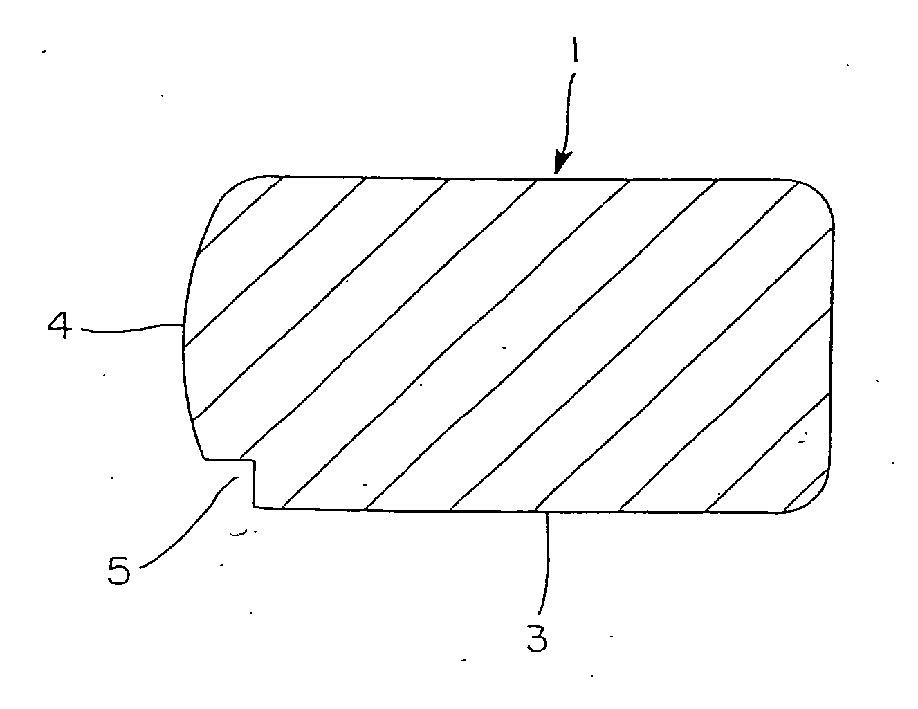
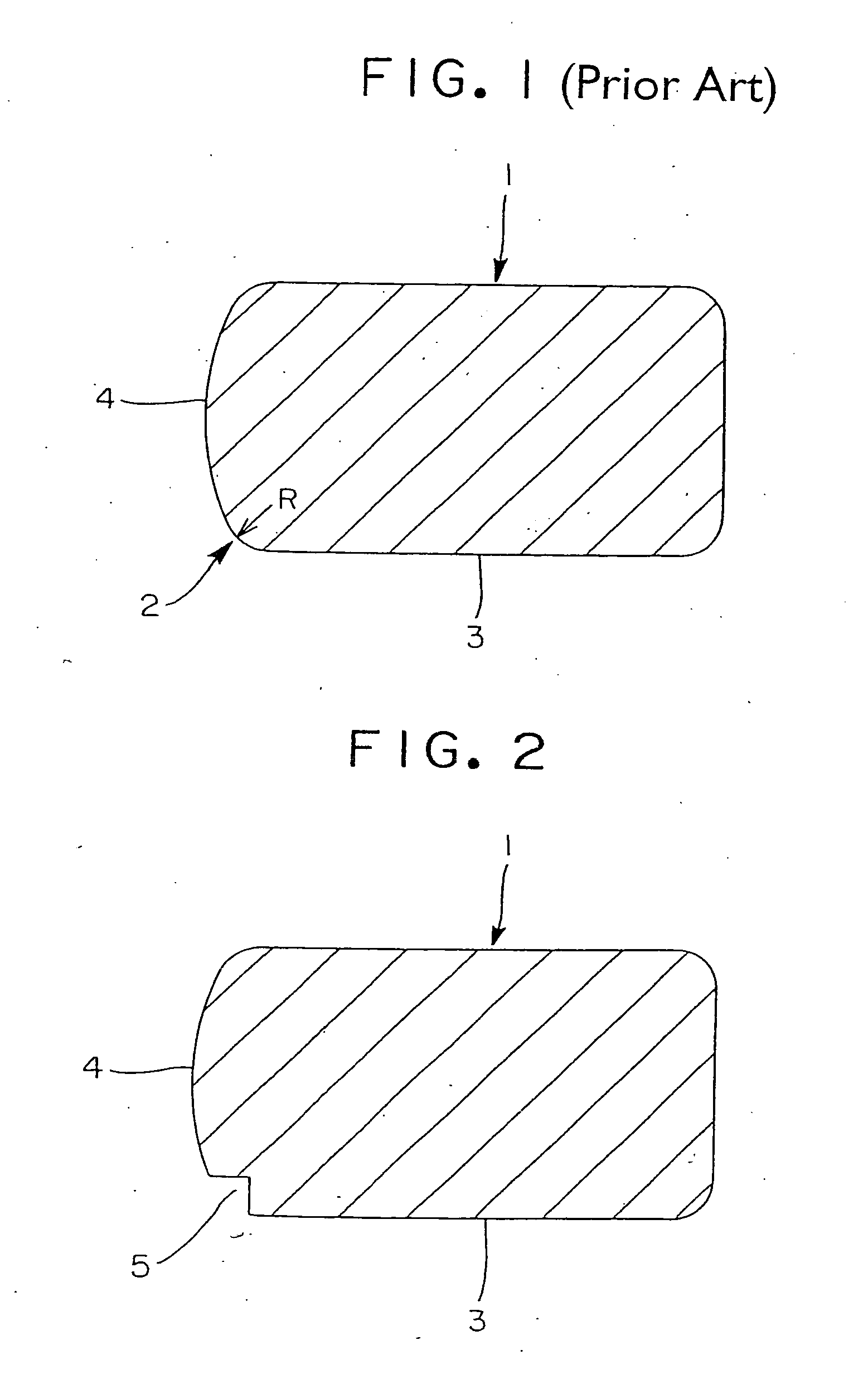
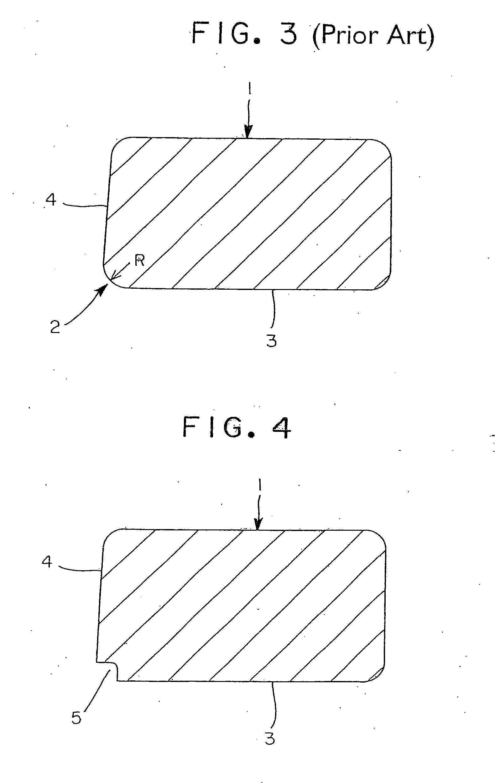
In a corner portion (2) defined between an outer peripheral surface (4) and a lower-side surface (3) of a steel piston ring (1), a groove (5, 6) having either an approximately quadrangular shape with a length of one side of 0.05 to 0.4 mm or an approximately quarter circular shape having a radius of 0.05 to 0.4 mm is formed. A sharp edge (9) formed by the groove (5, 6) performs an oil scraping function and the groove (5, 6) works to reduce an oil pressure of a second land or a third land clearance between the cylinder bore and the piston.

Description

[0001] This application is a division of U.S. patent application Ser. No. 10 / 380,799 filed Apr. 2, 2003, which is a 371 of international application PCT / JP02 / 07741, which claims priority based on Japanese patent application Nos. 2001-234894 and 2002-139028 filed Aug. 2, 2001, and May 14, 2002, respectively, which are incorporated herein by reference.TECHNICAL FIELD [0002] The present invention relates to piston ring, and more particularly to an improved piston ring made of a steel material. BACKGROUND ART [0003] A piston ring used in a reciprocating internal combustion engine is, based on a function thereof, classified into a pressure ring and an oil ring. In an automobile engine or the like, the pressure rings are generally composed of a first pressure ring which is positioned closest to a combustion chamber side and a second pressure ring which is positioned at a side below the first pressure ring (crank chamber side). [0004] The first pressure ring is positioned close to the comb...

Claims


Application Information

Patent Timeline
IPC IPC(8): F02F5/00F16J9/20
CPCF16J9/206F02F5/00
Inventor YOSHIDA, HIDEKISATO, AKIRAHELLE, ROLF
Owner RIKEN CO LTD
Learn More