Disk array apparatus and power backup method for the same

a technology of disk array and power backup method, which is applied in the direction of combination recording, dc source parallel operation, record information storage, etc., can solve the problems of power supply abrupt stop, difficult to make an investment to provide redundancy to their power supply system, and difficult to make such redundancy provision space in the power supply system. , to achieve the effect of reducing power loss, less space occupation in the disk array apparatus, and reducing power loss

Active Publication Date: 2005-08-18
GOOGLE LLC
View PDF19 Cites 21 Cited by
  • Summary
  • Abstract
  • Description
  • Claims
  • Application Information

AI Technical Summary

Benefits of technology

[0026] As such, according to the present invention, realized are higher energy efficiency and less space occupation in disk array apparatuses through reducing power loss and optimizing power capacity setting for a secondary battery that is used for backup.

Problems solved by technology

The issue here is that, even with such technology development, there still remain some problems.
That is, not to cause power supply for the storage device to abruptly stop due to temporary interruption of commercial power, users have found it difficult to make an investment to provide redundancy to their power supply systems or to make a space in the power supply systems available for such redundancy provision.

Method used


Image

  • Disk array apparatus and power backup method for the same
  • Disk array apparatus and power backup method for the same
  • Disk array apparatus and power backup method for the same

Examples


first embodiment

[0045]FIG. 2 is a function block diagram of the disk array apparatus of the

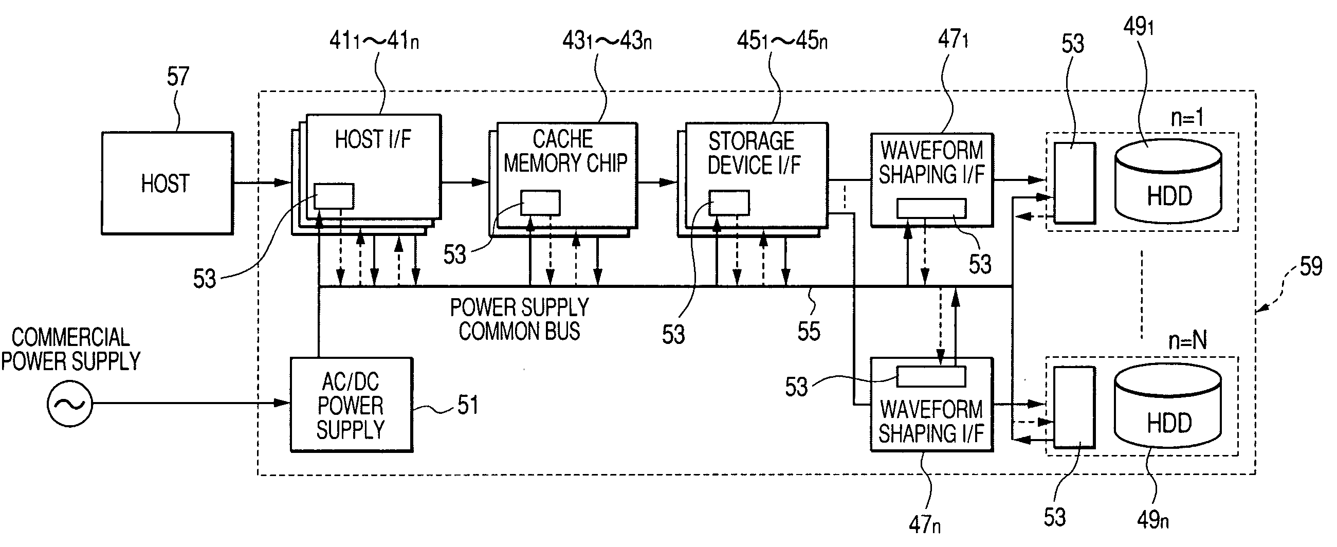
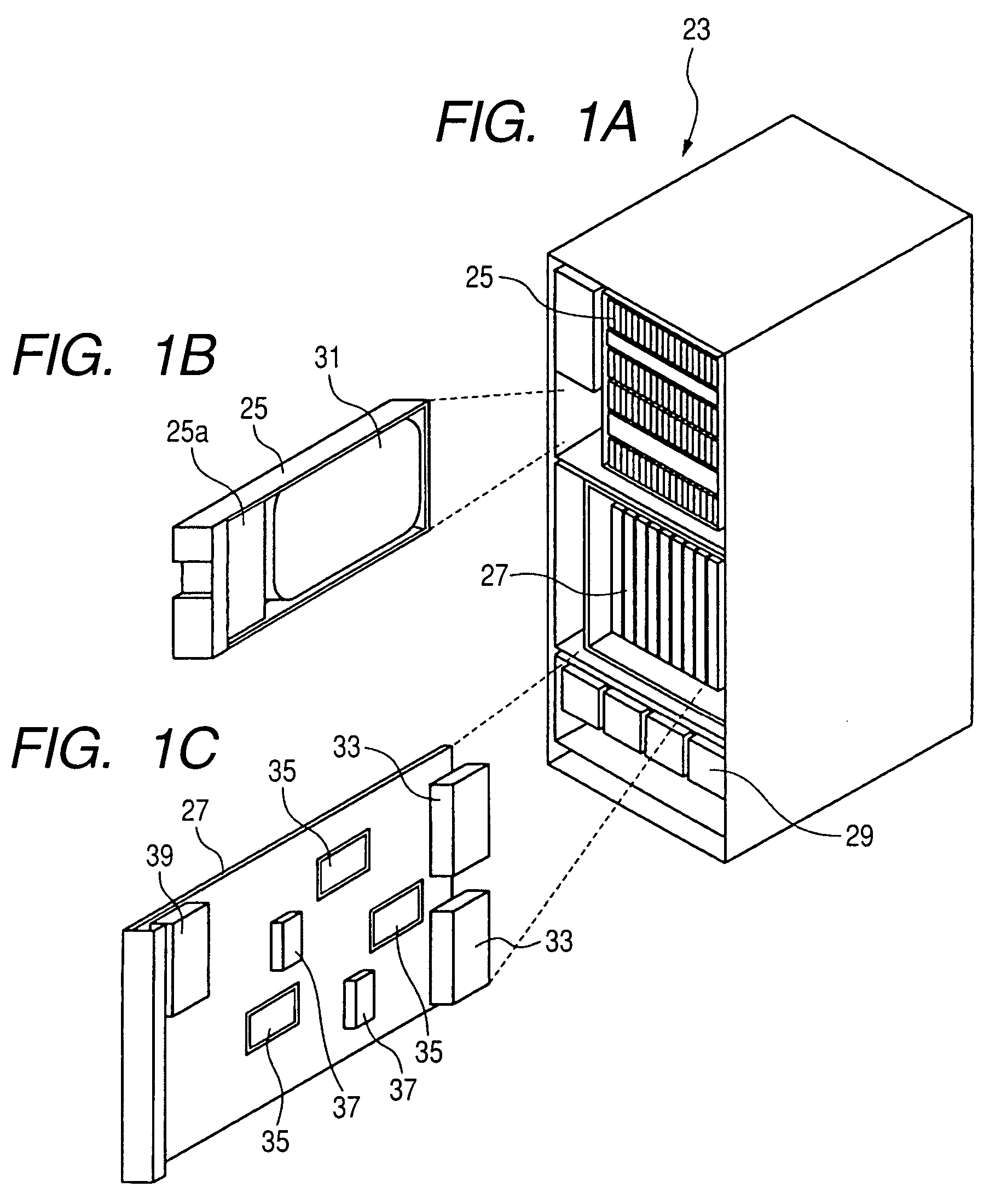
[0046] As shown in FIG. 2, the disk array apparatus is provided with a variety of specific logic circuit boards (27, FIG. 1), including: a plurality of host I / Fs (interfaces) 411 to 41n, a plurality of cache memory chips 431 to 43n, a plurality of storage device I / Fs 451 to 45n, a plurality of waveform shaping I / Fs 471 to 47n, a plurality of HDDs 491 to 49n, and an AC / DC power supply 51. A secondary battery box 53 is provided to each of the host I / Fs 411 to 41n, the cache memory chips 431 to 43n, the storage device I / Fs 451 to 45n, the waveform shaping I / Fs 471 to 47n, and the HDDs 491 to 49n.

[0047] The AC / DC power supply 51 converts alternating-current power provided by a commercial power supply to direct-current power of a predetermined level (hereinafter, referred to as “DC power”). The resulting DC power is provided, through a power supply common bus 55, to the host I / Fs 411 to 41n, the cache memory chip...

second embodiment

[0077]FIG. 6 is a function block diagram of a disk array apparatus according to the present invention.

[0078] In the structure of FIG. 6, the add-in secondary battery box 113 of FIG. 5E is connected to the power supply common bus 101, and the add-in secondary battery box 111 of FIG. 5B is provided in parallel to the HDD boxes 491 to 49n. These are the only differences from the structure of FIG. 2, and thus in FIG. 6, any component identical to that of FIG. 2 is provided with the same reference numeral and not described in detail again.

[0079] In the above structure, when the commercial power supply functions normally, the add-in secondary battery boxes 113 and 111 and other secondary battery box 53 store power that is supplied thereto from the AC / DC power supply 51 over the power supply common bus 55. Then, when the commercial power is interrupted, the power thus stored in the add-in secondary battery boxes 113 and 111 and in the secondary battery box 53 all flow out therefrom to the...


PUM

PropertyMeasurementUnit
DC voltageaaaaaaaaaa

Abstract

HDD boxes 831 to 83n are each incorporated with a secondary battery box 87, a non-isolated DC/DC converter 89, and an HDD 91. Logical circuit boards 851 to 85n are each incorporated with the secondary battery box 87, fast-transient-response-type non-isolated DC/DC converters 931 to 933, and a plurality of loads 951 to 953. Every secondary battery box 87 is provided with a charge/discharge circuit 97, and a plurality of in-line secondary batteries 99. In the HDD box, the output voltage from the secondary battery box 87 goes to an HDD 91 via the DC/DC converter 89. In the logical circuit board, the output voltage from the secondary battery box 87 goes to the corresponding loads 951 to 953 via the DC/DC converters 931 to 933. With such a structure, in a disk array apparatus, realized are higher energy efficiency and less space occupation through reducing power loss and optimizing power capacity setting for a backup power.

Description

CROSS REFERENCE TO RELATED APPLICATIONS [0001] This application relates to and claims priority from Japanese Patent Application No. 2004-035306, filed on Feb. 12, 2004, the entire disclosure of which is incorporated herein by reference. BACKGROUND OF THE INVENTION [0002] The present invention relates to a disk array apparatus including: a disk drive for storing data provided by an information processor; and cache memory for temporarily storing the data thus stored in the disk drive, and a power backup method for such a disk array apparatus. [0003] A disk array apparatus, i.e., a magnetic disk apparatus, has been conventionally in a cabinet structure. This is mainly for accommodating more magnetic disk modules, and increasing the packaging density thereof. In such a conventional magnetic disk apparatus, power supply is individually provided to a plurality of directors from a plurality of batteries provided specifically therefor. With respect to a plurality of magnetic disk modules to...

Claims


Application Information

Patent Timeline
Patent Type & Authority Applications(United States)
IPC IPC(8): G06F1/30G11B7/00G11B17/22G06F3/06G11B20/22G11B27/36G11B33/12
CPCG06F1/305G11B33/126G11B17/22
Inventor HAYASHI, KATSUNORI
Owner GOOGLE LLC
Why Eureka
Try Eureka