Photochemical hole burning media
a photochemical and burning media technology, applied in the field of optical memories, can solve problems such as limit the recording capacity, and achieve the effect of increasing the recording capacity
- Summary
- Abstract
- Description
- Claims
- Application Information
AI Technical Summary
Benefits of technology
Problems solved by technology
Method used
Image
Examples
example 1
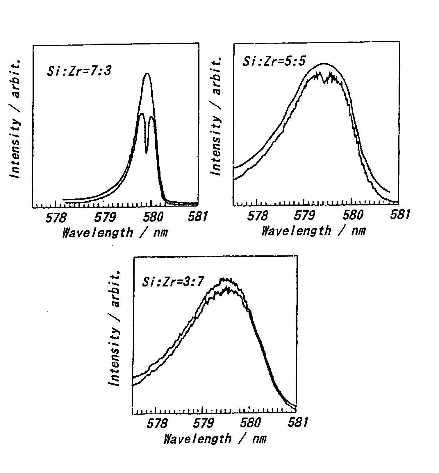
[0048] An optochemical hole burning medium using a solid matrix in which SiO2 was added to ZrO2 was prepared by the sol-gel method. The preparing procedure was as follows. A few or several drops of hydrochloric acid were added as a catalyst into a solution of Si(OC2H5)4:H2O:C2H5OH=1:1:5 (molar ratio), which was refluxed for one hour. Then, a metal alkoxide: Zr(OC2H5)4 was added to the resulting solution such that Si:Zr=7:3, 5:5 or 3:7, followed by one hour refluxing. EuCl3:H2O:C2H5OH=0.03:4:4:0.03 was added to the resultant, which was subjected to drying at 50° C. for 2 weeks or 90° C. for 2 days. Thereby, (SiO2—ZrO2):[Eu(15C5)]3+ was obtained.
[0049] After the resulting sample was cooled by using a cryostat, a hole was formed through being irradiated with laser beam of rhodamine 6G colarant at 100 mW / mm2 for 10 minutes. The stability of the hole was evaluated based on temperature cycles that the sample having a hole formed at 77K was heated to a given temperature, held at this temp...
example 2
[0055] Next, in order to clarify a cause for the high hole-maintaining temperatures of the above-mentioned composite glasses, R6G laser beams at an intensity of 300 mW / mm2 and a wavelength of 579.6 mm were irradiated upon SiO2:Eu(15C5)3+(EuCl3=3 mol %, 15C5=9 mol %) at room temperature for 2 hours, and fluorescent spectra were examined before and after the irradiation. Results of the fluorescent spectra are shown in FIGS. 3(a) and 3(b). As a result, it was clarified in the laser-irradiated samples that the intensity of light emission at 570˜720 nm based on Eu+3 ions decreased, whereas fluorescent peak based on Eu+2 ions newly appeared at around 420 nm.
[0056] From the above, it was suggested that the optical reduction from Eu3+ ions to Eu2+ ions was caused as the PSHB mechanism by the laser irradiation.
example 3
[0057] From the results stated in Example 2, it was clarified that the reduction from Eu3+ to Eu2+ can exhibit excellent hole-maintaining characteristic.
[0058] Thus, various reducing agents were dispersed in trial into solid matrixes together with rare earth complexes.
[0059] First, tests were performed with a silane compound being used as a reducing agent. More specifically, SiO2:Eu(15C5)3+, Me3SiSiMe3 was prepared. The preparing procedure was as follows. A few or several drops of hydrochloric acid were added as a catalyst into a solution of Si(OC2H5)4:H2O:C2H5OH=1:1:5 (molar ratio), which was refluxed for one hour. Then, EuCl3:H2O:C2H5OH:15C5:Me3=0.03:4:4:0.03:0.06 (molar ratio) were added to the resulting solution, which was subjected to drying at 50° C. for one week or at 90° C. for 2 days. Thereby, SiO2:Eu(15C5)3+, Me3SiSiMe3 was obtained. Loaded compositions for typical glass materials are shown in Table 1.
TABLE 1Loaded composition for the typical glass materialsTEOS (1:1:5...
PUM
| Property | Measurement | Unit |
|---|---|---|
| oxidation/reduction potential | aaaaa | aaaaa |
| oxidation/reduction potential | aaaaa | aaaaa |
| temperature | aaaaa | aaaaa |
Abstract
Description
Claims
Application Information
 - R&D
- Intellectual Property
- Life Sciences
- Materials
- Tech Scout
- Unparalleled Data Quality
- Higher Quality Content
- 60% Fewer Hallucinations
Browse by: Latest US Patents, China's latest patents, Technical Efficacy Thesaurus, Application Domain, Technology Topic, Popular Technical Reports.
© 2025 PatSnap. All rights reserved.Legal|Privacy policy|Modern Slavery Act Transparency Statement|Sitemap|About US| Contact US: help@patsnap.com


