
Cross talk and EME minimizing suspension design

a technology of crosstalk and suspension design, applied in the direction of integrated arm assemblies, maintaining head carrier alignment, instruments, etc., can solve the problems of crosstalk coupling complicating the design of higher density disk drives, and complicating the design of magnetic head suspensions, so as to reduce crosstalk interference

Inactive Publication Date: 2005-08-18
HEADWAY TECH INC
View PDF23 Cites 44 Cited by
  • Summary
  • Abstract
  • Description
  • Claims
  • Application Information

AI Technical Summary

Benefits of technology

[0009] It is therefore an object of the present invention to provide a structure and a method for minimizing the crosstalk and EME between the signal lines on a trace suspension assembly which are used to write and read the tracks of magnetic disk drives. It is further an object of this invention to provide alternative implementations of this structure and method in order to minimize the crosstalk and EME in various uses of the trace suspension assembly.
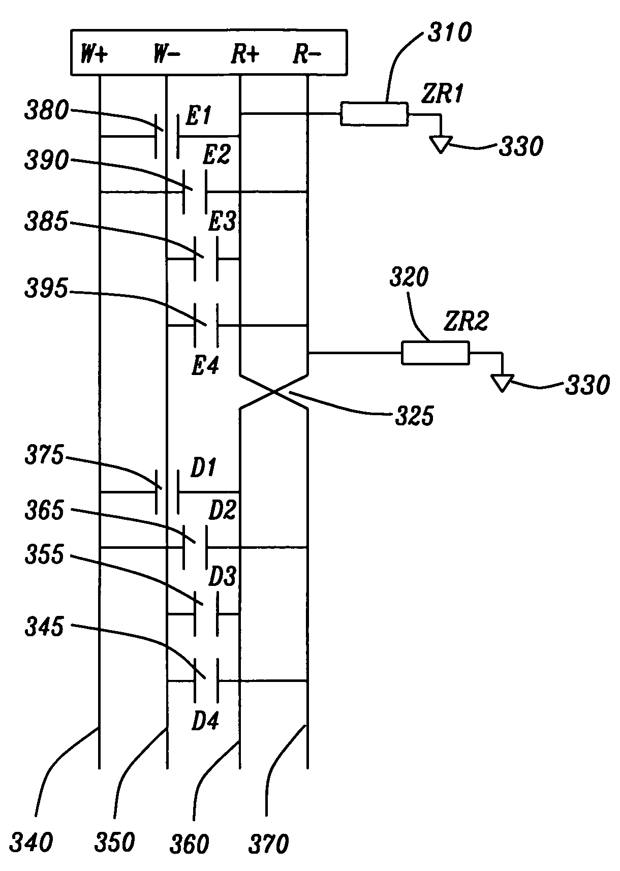
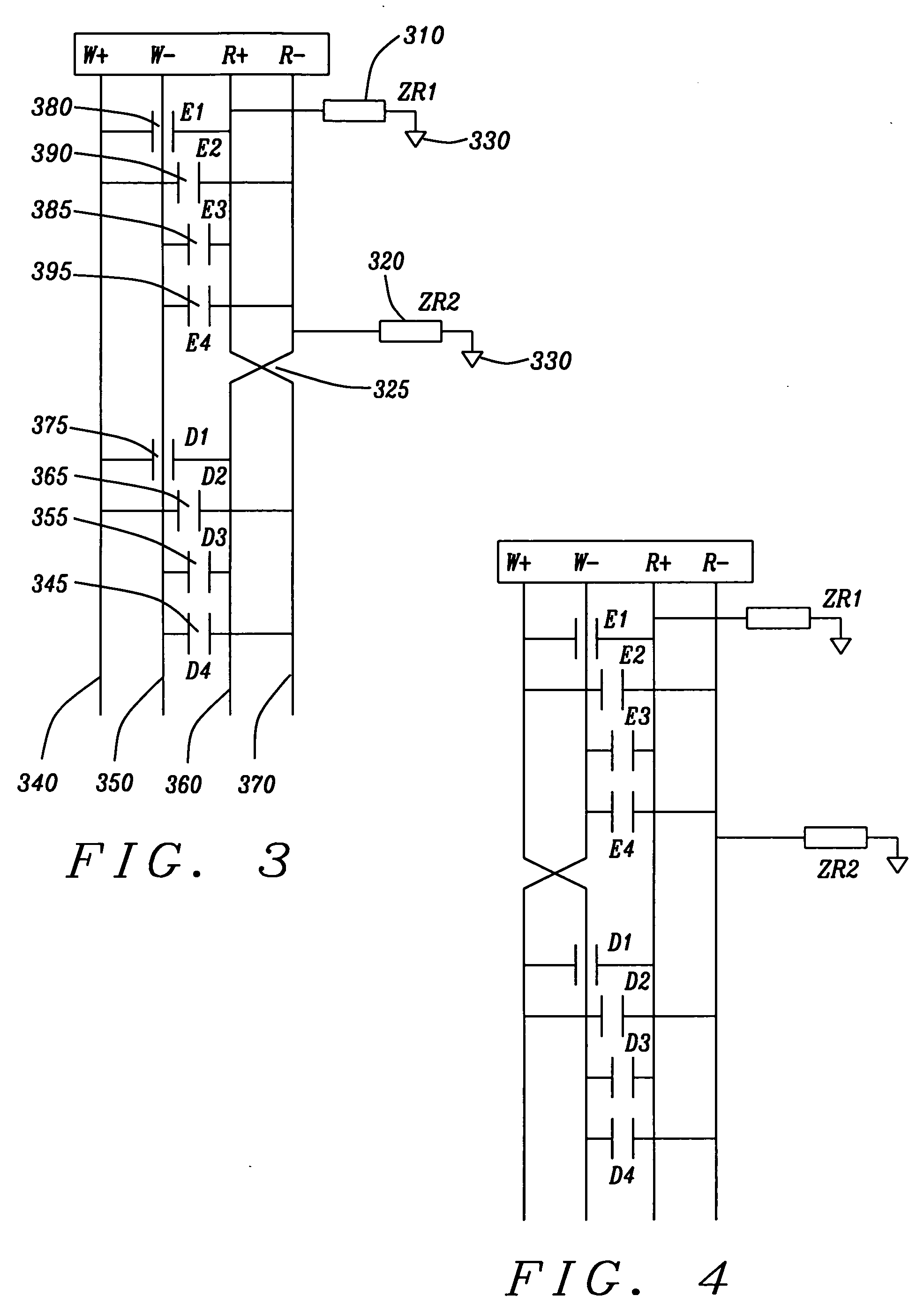
[0010] The objects of this invention are achieved by a crosstalk and EME minimizing trace suspension assembly structure comprising multiple write lines which are crossed between said preamplifier connection point and said slider contact pads, multiple read lines driven by pre-amplifier circuits, slider contact pads, which connect said write lines to said trace suspension assembly, slider contact pads, which connect said read lines to said trace suspension assembly and multiple write line driven by preamplifierlifier circuits.
[0011] The objects of this invention are further achieved by placing the crossing point of the write lines halfway between the preamplifier connection point and the slider contact pads. In addition, the crossing point of the write line is made by the addition of a second metallization layer onto said trace suspension assembly. The crosstalk and EME minimizing structure of this invention can also use multiple crossing points of the write lines in order to further cancel out time-delayed (transmission line effects) parts of the crosstalk.

Problems solved by technology

These more closely spaced tracks complicate the design of the magnetic head suspensions, which are used to accurately & quickly position the read and write heads over the required information track on the magnetic disk.
This crosstalk coupling complicates the design of higher density disk drives (Includes summary of 3 prior art dockets here).

Method used


Image

  • Cross talk and EME minimizing suspension design
  • Cross talk and EME minimizing suspension design
  • Cross talk and EME minimizing suspension design

Examples


Embodiment Construction

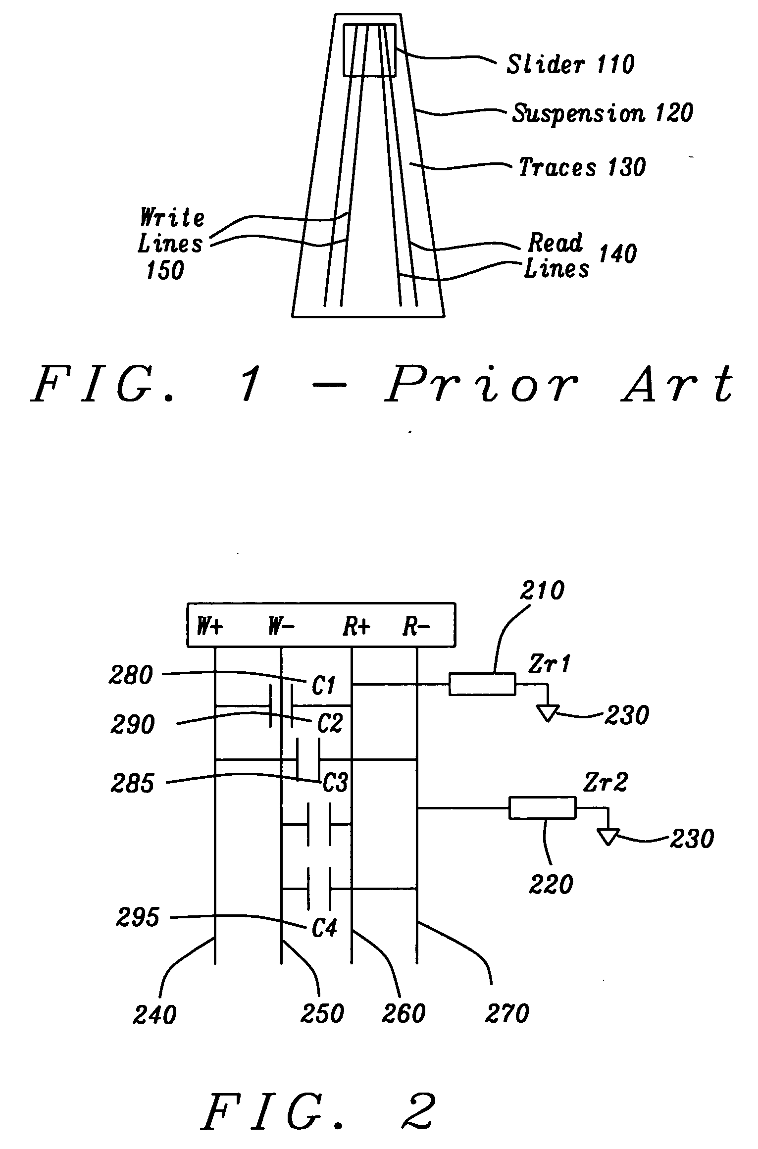
[0017]FIG. 2 shows a schematic known to the inventor. It is a representation of capacitive coupling between the write and read lines on the trace suspension assembly. This figure shows two impedances ZR1 (210) and ZR2 (220). Both of these impedances go to ground 230. These impedences ZR1 and ZR2 are a combination of trace suspension and preamplifier circuit. The other end of the ZR1 (210) impedance is connected to the Read+, R+, line 260. The other end of the ZR2 (220) impedance is connected to the Read−, R−, line 270.

[0018]FIG. 2 also shows capacitors, which represent the capacitive coupling between the Read and Write lines. Capacitor, C1280 represents the capacitive coupling between the Write+, W+, line 240 and the Read+, R+, line 260. Capacitor, C2, 290, represents the capacitive coupling between the Write+, W+line 240 and the Read−, R−, line 270. Capacitor, C3, 285, represents the capacitive coupling between the Write−, W− line 250 and the Read+, R+line 260. Capacitor, C4, 295,...


PUM


Abstract

This structure and method for minimizing EME (Electromagnetic Emission) and the crosstalk between the signal lines which are used to write and read the tracks of magnetic disk drives. These signal lines are located on magnetic trace suspension assemblies which move above the magnetic disk drives. The structure and method utilize well-placed single and multiple crossovers on either or both of the lines used to read and write the tracks on magnetic disks. In addition, the structure and method utilize the parasitic capacitances between the write and read lines to couple beneficial voltages which cancel the unwanted crosstalk noise.

Description

BACKGROUND OF THE INVENTION [0001] 1. Field of the Invention [0002] The present invention generally relates to the general field of magnetic trace suspension assemblies for magnetic disk drives. More particularly, this invention relates to a structure and a method for minimizing the crosstalk between the signal lines which are used to write and read the tracks of magnetic disk drives, and Electromagnetic Emission (EME) from the drive. [0003] 2. Description of the Prior Art [0004]FIG. 1 shows a prior art magnetic trace suspension assembly, with the slider 110 and the four trace 130 connecting the two read 140 lines and the two write lines 150. Prior art disk drives contain disk drive suspensions, which support magnetic heads. These read / write heads are held above information tracks, which are contained in rotating magnetic disks within the disk drives. [0005] As the density of disk drives increases in each new generation of storage devices, the density of the information tracks on th...

Claims


Application Information

Patent Timeline
IPC IPC(8): G11B5/48G11B21/21G11B5/60
CPCG11B5/486G11B5/484
Inventor DOVEK, MORISHU, DAVID
Owner HEADWAY TECH INC
Learn More