
Buffered oversampling analog-to-digital converter with improved DC offset performance

an analog-to-digital converter and offset performance technology, applied in the field of buffered oversampling analog-to-digital converters with improved dc offset performance, can solve the problems of ineffective offset drift correction techniques, increased chopper frequency, and non-ideal chopper amplifier switches, etc., to reduce dc offset and offset drift, and high and constant input impedance

Active Publication Date: 2005-08-18
ANALOG DEVICES INT UNLTD
View PDF20 Cites 12 Cited by
  • Summary
  • Abstract
  • Description
  • Claims
  • Application Information

AI Technical Summary

Benefits of technology

This patent describes an improved analog-to-digital converter that has reduced DC offset and offset drift, and a high and constant input impedance. Additionally, it does not require a digital chopper stage and uses a low noise external amplifier / buffer while maintaining exceptional DC accuracy for the overall converter. The user can optimize the converter by inserting a customized buffer / amplifier between an analog chopper and a signal processing chain, resulting in a buffered analog-to-digital converter with both low input noise and very good DC accuracy.

Problems solved by technology

Nevertheless, the non-ideal chopper amplifier switches contribute DC offset and offset drift proportional to the chopper frequency, which corresponds to the relatively high sampling frequency of the Δ-Σ modulator.
Although digital calibration techniques may be used to remove residual DC offset, such techniques are ineffective for correcting offset drift.
Such increases, however, require that the chopper frequency also must increase, which increases residual offset and offset drift.
For high accuracy oversampling converters (i.e., converters that evaluate the input signal at rates much higher than the conversion rate) this presents a difficult requirement.
However, in each of these proposed solutions that include an input buffer, a compromise is met between DC accuracy and input noise level.

Method used


Image

  • Buffered oversampling analog-to-digital converter with improved DC offset performance
  • Buffered oversampling analog-to-digital converter with improved DC offset performance
  • Buffered oversampling analog-to-digital converter with improved DC offset performance

Examples


Embodiment Construction

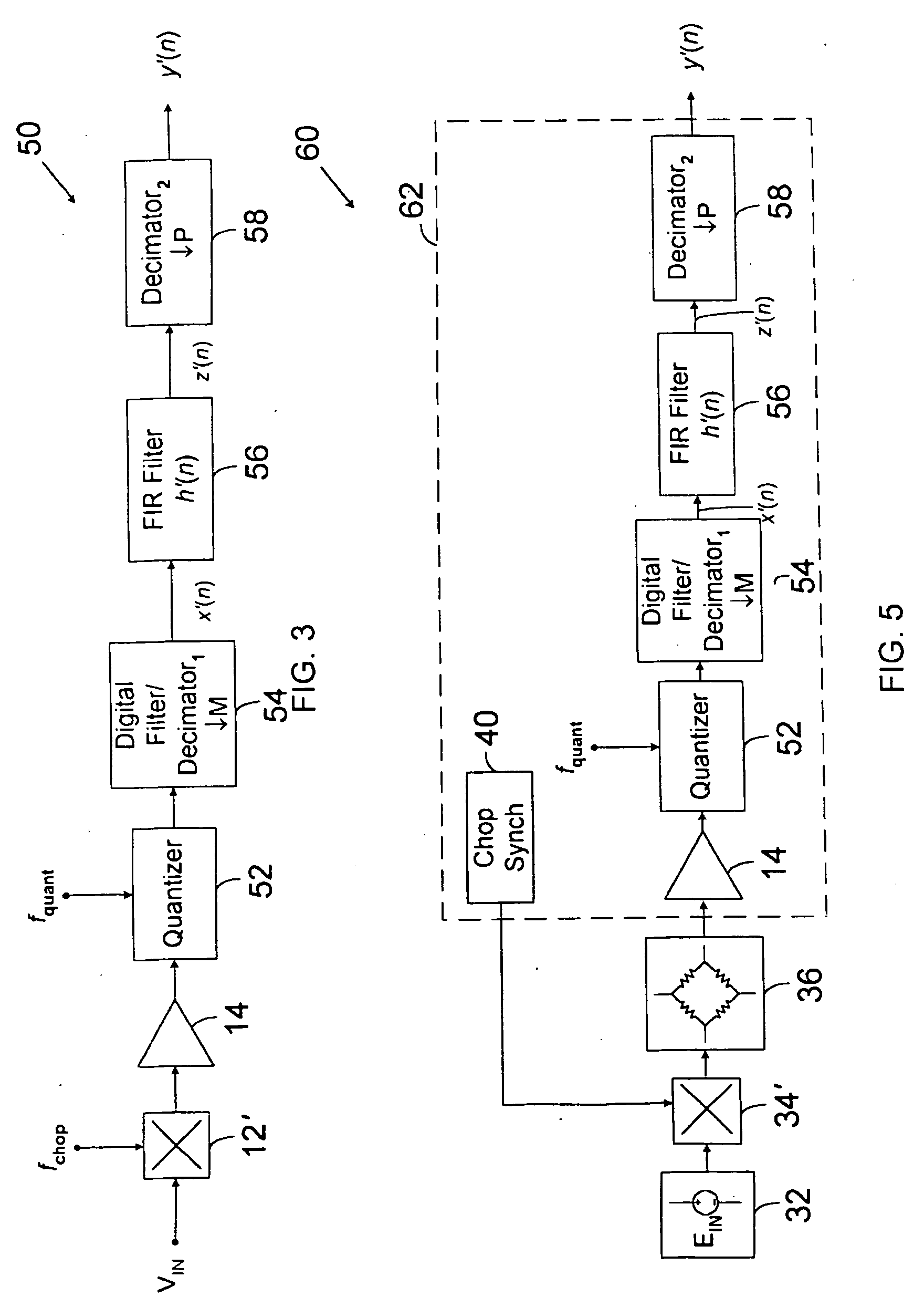
[0028] Referring to FIG. 3, an A / D converter is described. A / D converter 50 includes analog chopper 12′, buffer amplifier 14, quantizer 52, digital filter and decimator1 54, FIR filter 56 and decimator2 58.

[0029] Analog chopper 12′ chops analog input signal VIN with a square wave of frequency fchop, which successively reverses the polarity of VIN. Analog chopper 12′ may be implemented using any well-known analog chopping circuitry. For example, as shown in FIG. 4, if input signal VIN is a differential signal VIN=(VIN+−VIN−), analog chopper 12′ may be implemented using cross-coupled switches 24, 25, 26, and 27. Switch 26 is controlled by complementary chop signal {overscore (Q)}, and is coupled between VIN+ and VCOUT−. Switch 27 is controlled by complementary chop signal Q, and is coupled between VIN− and VCOUT+. Chop signals Q and {overscore (Q)} are complementary logic signals of frequency fchop. For example, when Q is HIGH and {overscore (Q)} is LOW, VCOUT+=VIN+, and VCOUT−=VIN−....


PUM


Abstract

The invention provides methods and apparatus for improving the direct current (DC) offset performance of an oversampling analog-to-digital (A / D) converter, including A / D converters that include an oversampling quantizer such as a single or multi-bit Δ-Σ modulator, successive approximation quantizer, flash quantizer, pipelined quantizer or other suitable oversampling quantizer. A customized buffer / amplifier may be inserted between an analog chopper and a signal processing chain. The customized buffer / amplifier is optimized for input noise and the signal chain compensates for poor DC performance. The result is a buffered analog-to-digital converter with both low input noise and very good DC accuracy.

Description

BACKGROUND OF THE INVENTION [0001] Converting a continuous-time analog signal to a discrete-time digital representation typically requires anti-alias filtering, sampling and quantization. An anti-aliasing filter ensures that analog input signal is properly band-limited prior to sampling. A sampler captures samples of the filtered input signal at discrete time intervals T=1 / Fs, where Fs is the sampling frequency. Sampling frequency Fs typically is selected as at least twice the bandwidth of the filtered analog input signal. A quantizer converts the samples to a discrete set of values. Conventional analog-to-digital (A / D) converters typically perform sampling and quantization, whereas separate discrete components or integrated circuits perform anti-aliasing. [0002] Oversampling A / D converters, in contrast, sample an analog input signal at a rate NFs that is many times greater than twice the bandwidth of the analog input signal. An oversampling converter typically includes an anti-alia...

Claims


Application Information

Patent Timeline
Patent Type & Authority Applications(United States)
IPC IPC(8): H03M1/12H03M3/00
CPCH03M3/458H03M3/34
Inventor OPRESCU, FLORIN A.
Owner ANALOG DEVICES INT UNLTD
Learn More