
Apparatus and method for electrostatic spray coating of medical devices

a technology of electrostatic spray and medical devices, applied in the direction of packaging foodstuffs, packaged goods types, pharmaceutical containers, etc., can solve the problems of insufficient elimination of conductivity variability, disadvantageous internal electrode arrangement, and inability to completely eliminate conductivity variability, so as to improve the ionization of coating fluid, increase the fraction of coating spray attracted, and increase the electrode surface area

Active Publication Date: 2005-08-11
BOSTON SCI SCIMED INC
View PDF8 Cites 90 Cited by
  • Summary
  • Abstract
  • Description
  • Claims
  • Application Information

AI Technical Summary

Benefits of technology

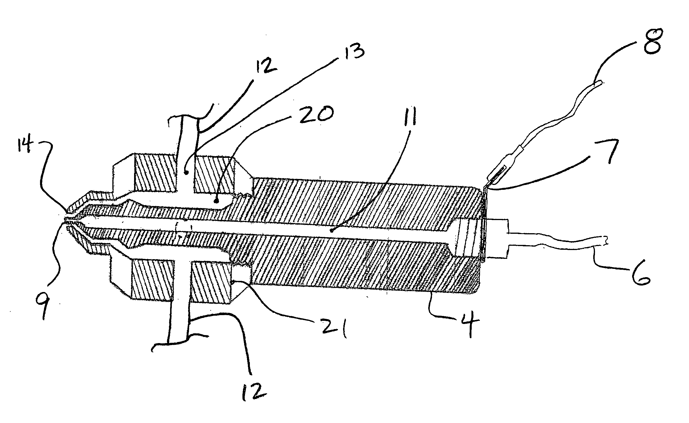
[0010] In certain embodiments of the invention, there is a provided an apparatus in which the coating fluid spray dispenser outlet nozzle comprises an electrically conductive material, and the second electrical potential is applied directly to the outlet nozzle to cause the coating fluid to be accelerated toward the target. This approach to electrostatic coating spray permits the entire dispenser and outlet nozzle to serve as the electrode for application of the second potential to the coating fluid, increasing the available electrode surface area within the nozzle in contact with the coating fluid, and thereby improving the coating fluid ionization. The increased ionization increases the fraction of coating spray attracted to the target.
[0012] The present invention provides the desired target with contact point uniformity and increased electrical attraction, thus improving coating material transfer to a target in a more cost-efficient manner.

Problems solved by technology

Such variability could be detrimental to obtaining consistent coating distribution and thickness on the target.
Experimentation with the attachment of high-conductivity materials to the target, such as gold or gold-plated electrodes, to enhance holder-to-target conductivity has not completely eliminated the variability in conductivity.
The internal electrode arrangement is disadvantageous, however, as it limits the amount of charge than may be efficiently transferred to the coating fluid spray.
Moreover, an internal electrode arrangement increases the complexity of the internal arrangements of the nozzle, while the amount of space available for the internal electrode is limited by other nozzle internal parts.
Other disadvantages of internal electrode-type nozzles are increased dispenser manufacturing costs, and increased difficulty in properly cleaning the electrode and the other parts within the dispenser.
Further, as a consequence of the internal electrode dispensing nozzle's internal geometry limiting electrode surface area, the amount of charge transfer from the internal electrode to the coating fluid is also limited.
The result is a lower overall coating utilization rate, and undesired waste of coating fluid.

Method used


Image

  • Apparatus and method for electrostatic spray coating of medical devices
  • Apparatus and method for electrostatic spray coating of medical devices
  • Apparatus and method for electrostatic spray coating of medical devices

Examples


Embodiment Construction

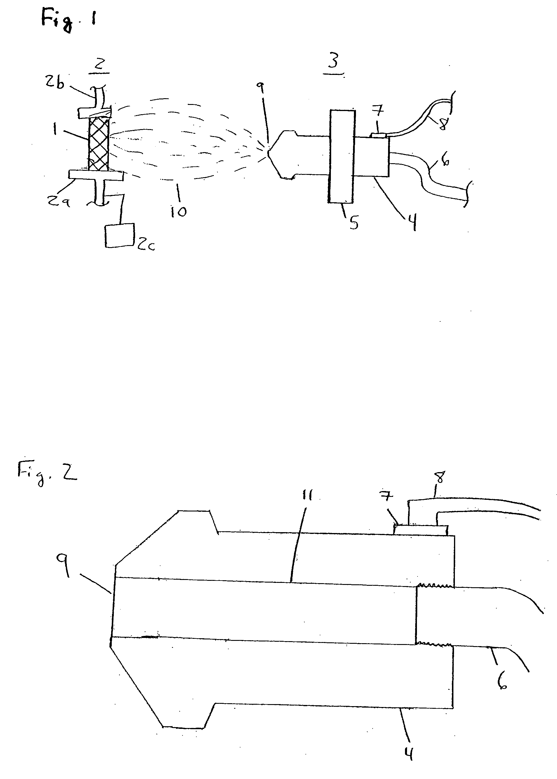
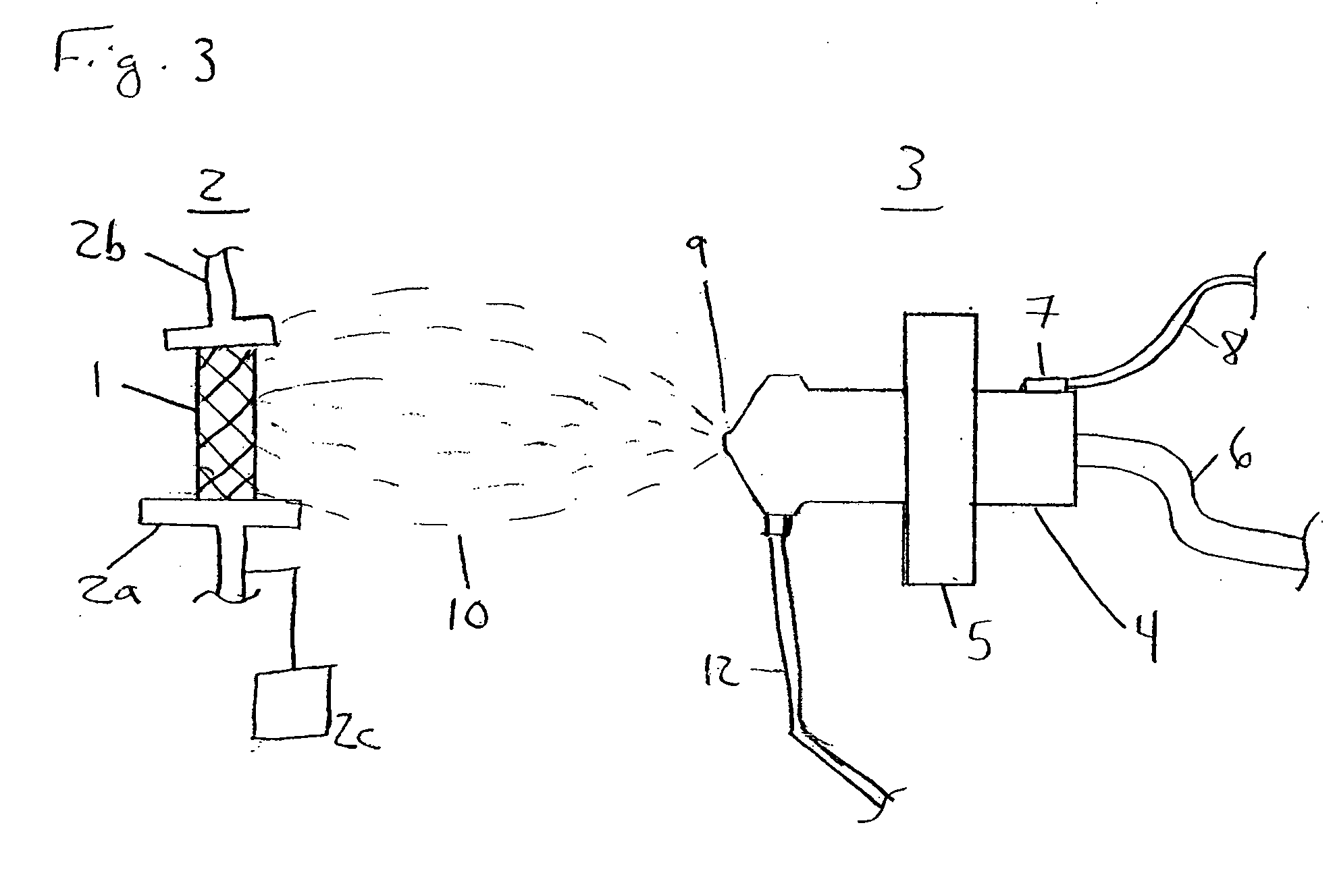
[0017] A first embodiment of the present invention is illustrated in FIG. 1. In this embodiment, a target 1 to be coated with a coating fluid is held by target holder 2, comprising a base portion 2a and a top portion 2b. Target 1 in this instance is a stent that is to be coated with a therapeutic material. In addition to holding stent 1 in a position suitable for coating application, stent holder base portion 2a functions as an electrode, and is maintained at a first electrical potential. Stent holder 2 may hold stent 1 by any number of means, such as by the stent holders described in U.S. patent application Ser. No. 10 / 198,094, the disclosure of which is hereby expressly incorporated by reference herein.

[0018] In this embodiment, stent holder 2 and stent 1 are held at a ground potential during electrostatic spraying of the coating fluid toward stent 1. In order to enhance the electrostatic attraction of the coating fluid to the target, after stent 1 is seated on stent holder 2 and...


PUM

PropertyMeasurementUnit
viscosityaaaaaaaaaa
voltageaaaaaaaaaa
thickaaaaaaaaaa

Abstract

An apparatus and method for electrostatic spray deposition of small targets, such as medical devices like stents. The apparatus includes a target holder which applies a first electrical potential to the target, and an electrostatic dispensing nozzle which applies a second potential sufficient to attract the coating fluid from the nozzle toward the target. Because the entire dispensing nozzle is conductive, the coating fluid may receive a greater charge than may be obtained with internal electrode-type nozzles. Electrostatic attraction of the coating fluid to the target is enhanced by the combination of higher charge density imparted to the coating fluid by the conductive nozzle, and application of a momentary voltage spike to the target to provide consistent conductivity between the target and its holder, thereby ensuring the target is presents the full first potential applied to the holder. The voltage spike may also be used independently of the conductive nozzle.

Description

FIELD OF THE INVENTION [0001] The field of the present invention is application of coatings to target devices, such as medical devices. More specifically, the present invention is directed to the field of electrostatic spraying of a fluid, such as a therapeutic or protective coating fluid, to apply a coating to a target device. BACKGROUND [0002] Medical implants are used for innumerable medical purposes, including the reinforcement of recently re-enlarged lumens, the replacement of ruptured vessels, and the treatment of disease such as vascular disease by local pharmacotherapy, i.e., delivering therapeutic drug doses to target tissues while minimizing systemic side effects. Such localized delivery of therapeutic agents has been proposed or achieved using medical implants which both support a lumen within a patient's body and place appropriate coatings containing absorbable therapeutic agents at the implant location. Examples of such medical devices include catheters, guide wires, ba...

Claims


Application Information

Patent Timeline
Patent Type & Authority Applications(United States)
IPC IPC(8): B05B5/03B05B5/10
CPCB05B5/03Y10S118/11B05B5/10
Inventor WORSHAM, ROBERTHANSEN, JAMES G.
Owner BOSTON SCI SCIMED INC
Learn More