
Ice fishing shelter

a technology for ice fishing and shelters, applied in the field of portable shelters, can solve the problems of inability to provide a simple, efficient, practical and safe portable shelter, prior art portable, and large size of typical ice fishing huts, and achieve the effect of reducing the overall volume of space needed and reducing the vertical exposure of the structur

Inactive Publication Date: 2005-08-11
BLAIR DANIEL
View PDF17 Cites 2 Cited by
  • Summary
  • Abstract
  • Description
  • Claims
  • Application Information

AI Technical Summary

Benefits of technology

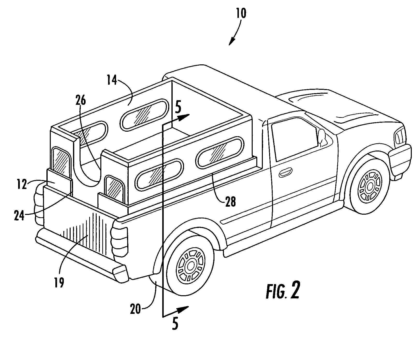
[0010] In this regard, the present invention provides for novel portable structure that is particularly suited for use in ice fishing. The general purpose of the present invention, which will be described subsequently in greater detail, is to provide a new and improved two piece structure that is particularly tailored for use as a portable ice fishing shelter. The structure's construction generally includes a lower shell and a separate removable cover unit installed onto the lower shell. Further, the lower shell is formed as a hull member having a floor surrounded by exterior sidewalls to define an interior well within the lower shell member. The cover unit is interfittingly received onto the walls of the sidewalls of the lower shell to complete the enclosure. The separability of the lower shell and the cover allow easy removal of the cover. When being transported, it is anticipated that the cover of the shelter be removed, inverted and placed within the lower shell thereby reducing the vertical exposure of the structure during transport as well as reducing the overall volume of space necessary for storing the shelter when not in use. Also, the construction of the shelter provides that when the two pieces are joined together a rigid lightweight structure is created that is capable of floating itself and its occupants in the event of an ice failure.
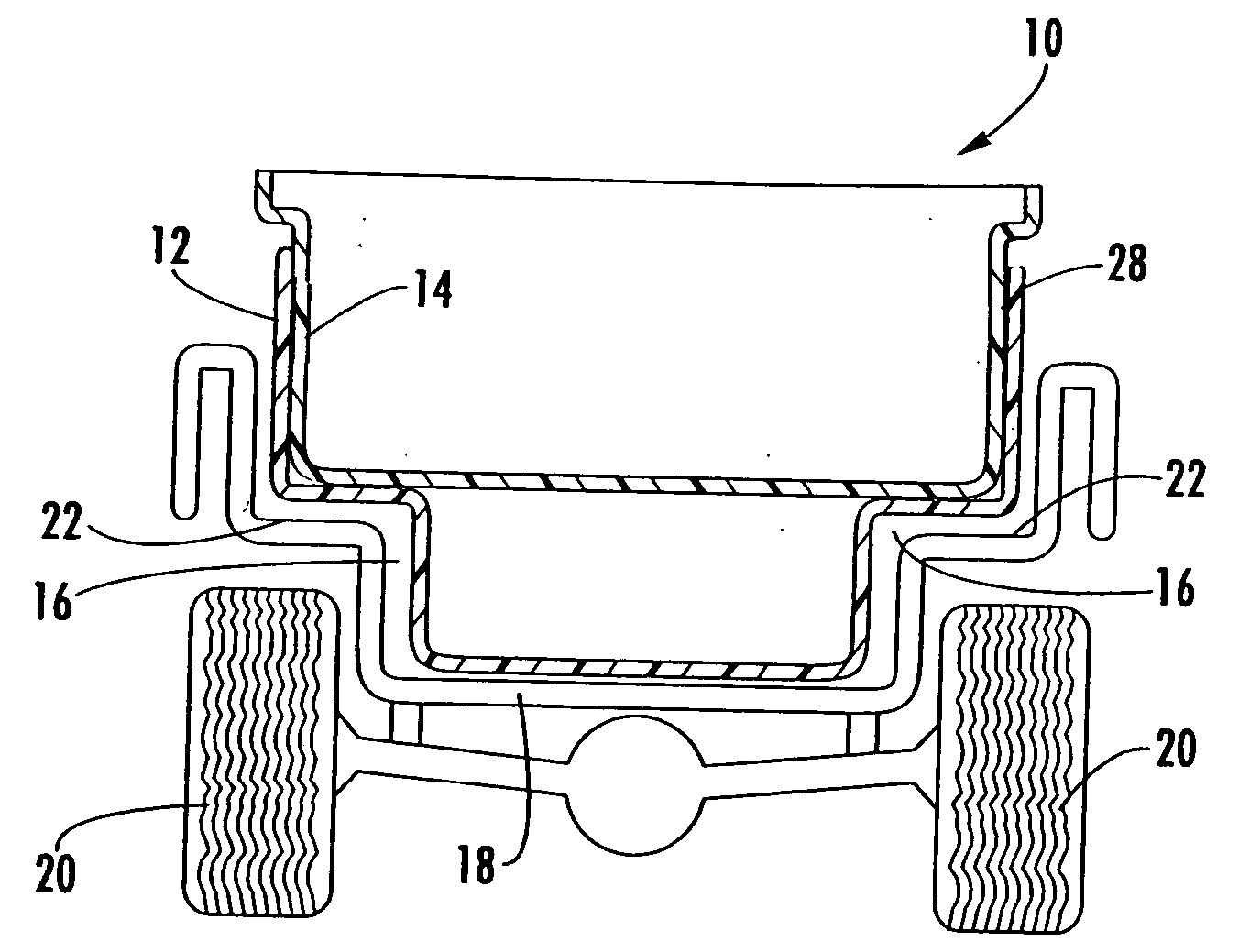
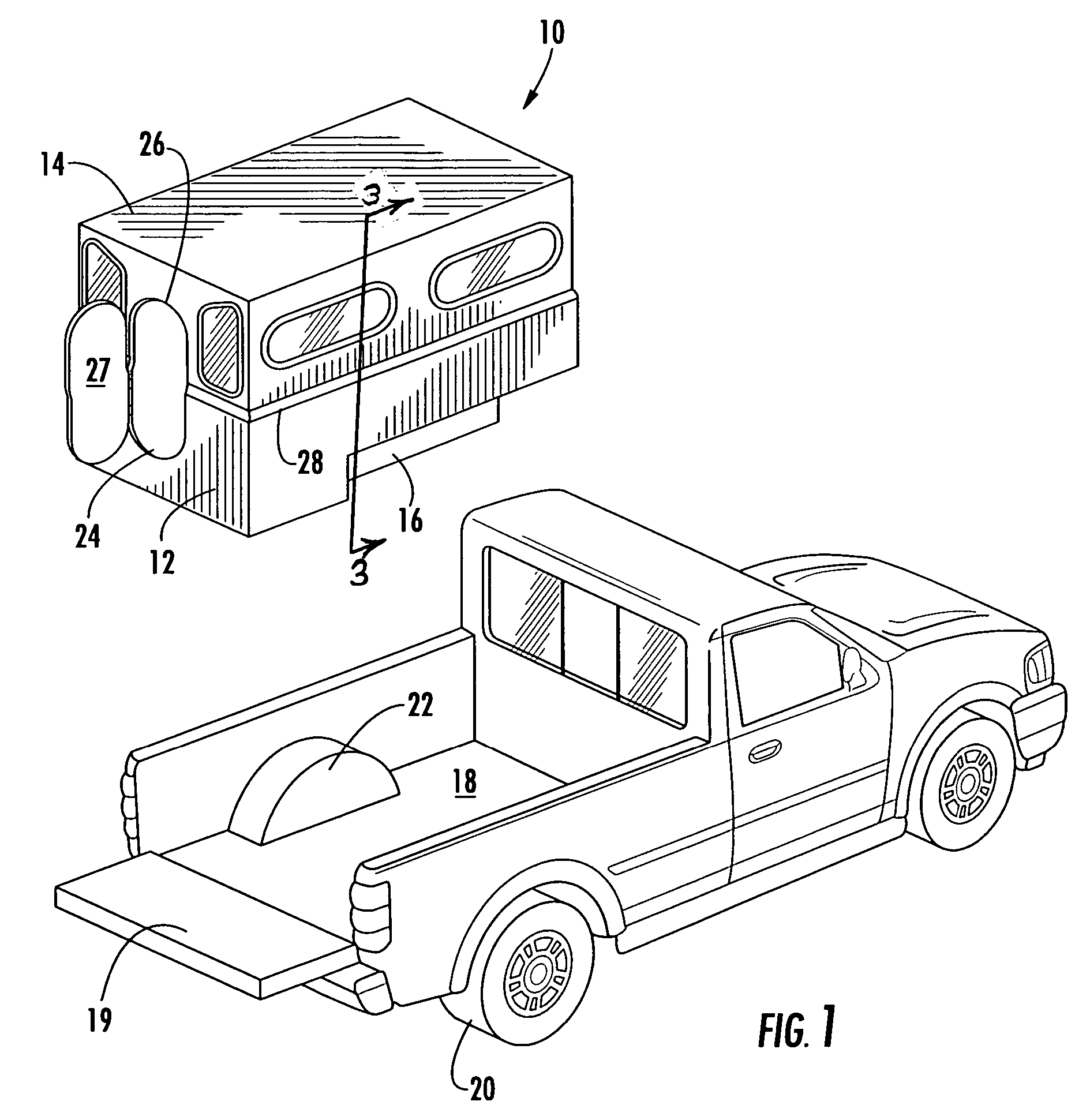
[0011] To further enhance the portability of the shelter of the present invention, the lower shell includes indentations along the lower sides thereof. These indentations serve two purposes. On the exterior, the indentations correspond to the location of the standard wheel well positions in a pickup truck bed. Accordingly the lower shell is configured and sized to be received into a pickup truck for easy transportation without having to disassemble the structure. Further, these areas also serve as convenient seating areas for the occupants within the structure when the structure is in use. The lower shell may also include an internal chamber for convenient storage of other items, such as fishing equipment.
[0013] It is therefore an object of the present invention to provide a sturdy and portable ice fishing shelter that is capable of protecting a plurality of users from the environmental conditions encountered while ice fishing. It is a further object of the present invention to provide an ice fishing shelter that can accommodate a plurality of users while being easily portable and reducible in size for transport and storage. It is yet a further object of the present invention to provide a portable ice fishing shelter that can accommodate a plurality of users and is tailored to interface with a pick-up truck bed whereby the device can be stored and easily transported to and from the ice fishing location. It is still a further object of the present invention to provide an ice fishing structure that enhances the safety of the users by serving as a flotation device in the event of catastrophic ice failure.

Problems solved by technology

A typical ice fishing hut is relatively large and is not portable.
Due to the cumbersome nature of this type construction, generally the shelter must be erected in place on the ice of a frozen lake, then disassembled and removed at the end of the ice fishing season.
The difficulty is that such prior art portable, collapsible shelters suffer from a variety of disadvantages.
While all of the aforementioned prior art constructions are more than adequate for the basic purpose and function for which they have been specifically designed, they are uniformly deficient with respect to their failure to provide a simple, efficient, practical and safe portable shelter that can be transported to and from a fishing spot while requiring a minimal amount of effort to erect and maintain the shelter once in position.
Additionally, while the presently available ice fishing shelters are somewhat successful, another shortcoming is that they generally provide only enough space to comfortably seat one occupant in the shelter.
Another shortcoming in the prior art is that If more than one fisherman is going on the expedition, several shelters must be provided, or a single shelter that is extremely cumbersome and unwieldy to transport, set up and use must be provided.
Such means of accommodating plural fisherman can also be expensive.
The devices are generally bulky and while means are provided to remove the structures from the pick-up truck bed are provided, they are generally intended to be set in place in the pick-up truck and used in conjunction therewith.
Further, these structures are large and in order to provide sufficient head room for the occupants of the structure, the structure must necessarily extend well above the roof line of the pick-up truck in which they are transported providing undesirable windage against these surfaces when transporting the structure over long distances.
Further, as most people who engage in ice fishing are all too well aware, variable ice conditions represent a very real and potential deadly danger that every year claims the lives of several participants in this otherwise enjoyable sport.
There is only one prior art portable shelter construction that is designed to keep the occupant of the shelter afloat when faced with catastrophic ice failure and this shelter is limited to a single occupant.

Method used


Image

  • Ice fishing shelter
  • Ice fishing shelter
  • Ice fishing shelter

Examples


Embodiment Construction

[0021] Now referring to the drawings, the portable ice fishing structure 10 of the present invention is shown and generally illustrated in the figures. The portable shelter 10 of the present invention is formed to include a bottom shell 12 and a top shell 14 where the bottom 12 and top 14 shell pieces interfit with one another to create the overall body of the shelter 10. Further, as can best be seen in FIG. 1, the bottom shell 12 of the shelter 10 is formed monolithically, as will be described in more detail below, and includes recesses 16 in the sides thereof to allow the bottom shell 12 to be placed into a pick-up truck bed 18 for the purposes of transportation. The top shell 14 is also monolithically formed and fits onto the bottom shell 12 to create a complete shelter 10 to protect the occupants of the shelter from the winter environment.

[0022] The present invention is particularly directed to a shelter 10 that is fully portable yet sturdy enough to protect occupants from the ...


PUM


Abstract

A portable structure for use in ice fishing is disclosed. The present invention provides a two piece structure that generally includes a lower shell and a separate removable hard cover shell that is installed onto the lower shell. Further, the lower shell is formed as a hull, having a floor surrounded by exterior sidewalls to define an interior well within the lower shell. The cover unit is interfittingly received onto the walls of the sidewalls of the lower shell to complete the enclosure. The separability of the lower shell and the cover allow easy removal of the cover. When being transported, the cover of the shelter is removed, inverted and placed within the lower shell to reduce the exposure of the structure during transport and reduce the volume of space necessary for storing the shelter when not in use. The construction provides that when the two pieces are joined together a rigid lightweight structure is created that is capable of floating itself and its occupants in the event of an ice failure.

Description

CROSS-REFERENCE TO RELATED APPLICATIONS [0001] This application is related to and claims priority from earlier filed U.S. Provisional Patent Application No. 60 / 542,778, filed Feb. 6, 2004, the contents of which are incorporated herein by reference.BACKGROUND OF THE INVENTION [0002] The present invention relates generally to portable shelters. More specifically, the present invention relates to a portable shelter that is particularly suited for ice fishing activities while being easily transported and having sufficient structure and mass to adequately protect the inhabitant from the inclement weather conditions generally associated with ice fishing. [0003] The sport of ice fishing has become extremely popular in recent times. Since ice fishing is performed outdoors in generally difficult weather conditions, the ice-fisherman usually requires some sort of shelter from the elements. Therefore, with the increase in popularity of ice fishing, there has been a corresponding increase in th...

Claims


Application Information

Patent Timeline
IPC IPC(8): B60P3/34B60P3/345B60P3/36
CPCB60P3/36B60P3/34
Inventor BLAIR, DANIEL
Owner BLAIR DANIEL
Learn More