Positioning structure of plane image input apparatus

a plane image and input apparatus technology, applied in the field of positioning structure, can solve problems such as failure of positioning, and achieve the effect of improving the accuracy of correcting color rank

Inactive Publication Date: 2005-08-04
MULLER CAPITAL
View PDF3 Cites 1 Cited by
  • Summary
  • Abstract
  • Description
  • Claims
  • Application Information

AI Technical Summary

Benefits of technology

The present invention aims to improve the accuracy of correcting color rank and positioning the correct picture of a plane image input apparatus. The technical effect of this invention is to enhance the accuracy of the positioning structure of the apparatus.

Problems solved by technology

The technical problem addressed in this patent text is the difficulty of accurately positioning a scanned document when using a correct picture to adjust color rank and positioning, due to space constraints on the upper side of the scanner. This problem can also affect copiers that use the correct picture for the same purposes.

Method used


Image

  • Positioning structure of plane image input apparatus
  • Positioning structure of plane image input apparatus
  • Positioning structure of plane image input apparatus

Examples


Embodiment Construction

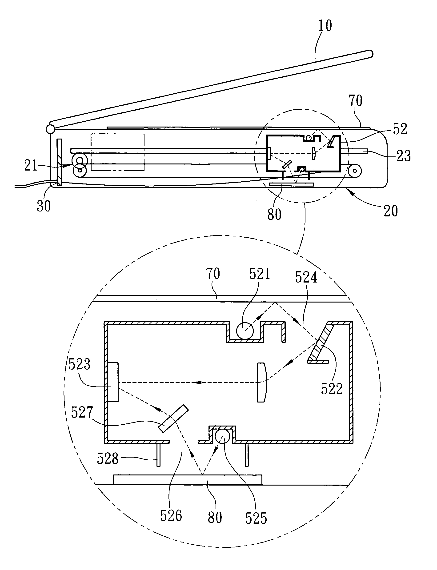
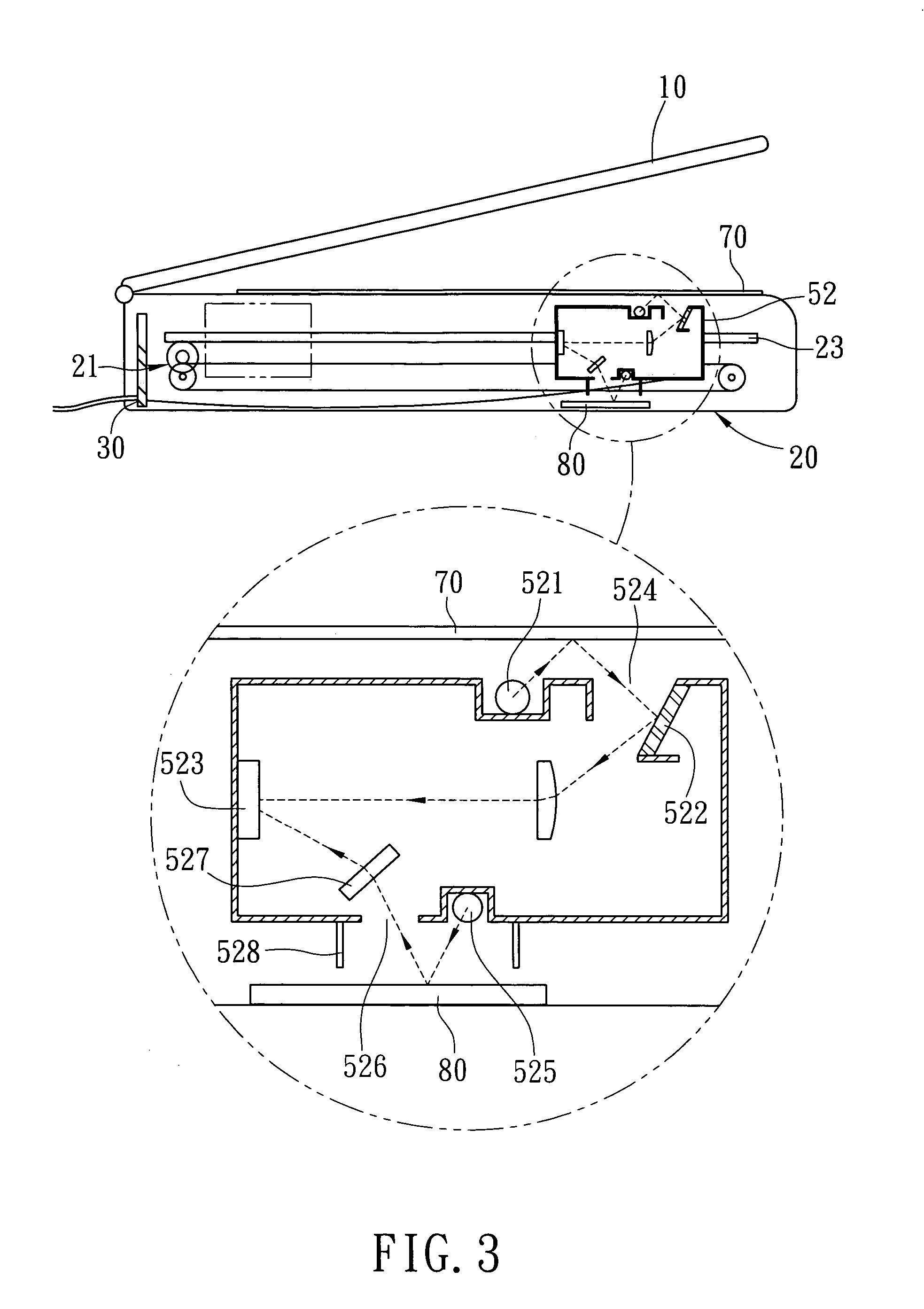
[0012] Referring to FIG. 3, the positioning structure of a plane image input apparatus according to the invention includes a lid 40, a body 50 and a printed circuit board (PCB) 60. The lid 40 is located on an outer side of one side of the body 50 for flattening a scanned document 70. The body 50 has a hollow interior to house the main mechanisms of the scanner, including a transmission mechanism 51, an optical module 52 and a guiding track 53. The scanned document 70 is located on the outer side of one side the body 50. The body 50 has another side holding a correct picture 80 therein. The transmission mechanism 51 drives the optical module 52 to move reciprocally along the guiding track 53. The optical module 52 includes a scan light source 521, a scan hole 524, a reflecting mirror set 522 and a charge-coupled device (CCD) 523. The scan light source 521 is located on the one side of the scanner corresponding to the scanned document 70. It emits light and projects the light to the s...


PUM


Abstract

A positioning structure of plane image input apparatus comprises a hollow body, carrying scanned documents and setting a correct picture on outer and inner opposite sides, and an optical module inside the body moving back and forth. The optical module has a correct light source to emit light, a correct hole for reflect light passing through and propagating to the optical module, a guiding mirror set to guide light, and a charge couple device to receive light. The correct light source and the correct hole are respect to the correct picture side of the body. After reflected by the correct picture, light passes the correct hole, to the optical module and is guided by the guiding mirror set to the charge couple device for the optical module to correct color rank and to position. Thus, the positioning structure improves accuracy of correcting color rank and positioning of the correct picture.

Description


Claims


Application Information

Patent Timeline
Owner MULLER CAPITAL
Why Eureka
Try Eureka