
Transmissive key sheet, input keys using transmissive key sheet and electronic equipment with input keys

Inactive Publication Date: 2005-08-04
LENOVO INNOVATIONS LTD HONG KONG
View PDF6 Cites 21 Cited by
  • Summary
  • Abstract
  • Description
  • Claims
  • Application Information

AI Technical Summary

Benefits of technology

[0009] It is therefore an object of the present invention to provide a transmissive key sheet enabling effective illumination with less quantity of light emitted from a light source and numbers of input keys to be disposed in a small area of small equipment by applying additional new processes to a resin film to produce various new effects while ensuring the thinness of the entire key sheet and suppressing the decrease of light transmission through the use of a combination of translucent resin and a resin film, input keys using the transmissive key sheet, and electronic equipment with the input keys.
[0024] As described above, in accordance with the present invention, the resin film having letters, symbols, etc. printed on its under surface on the side of the key tops, and the resin film on the side of the pressure applicators are formed separately. The transmissive key sheet is formed of the resin films bonded together with an adhesive. Thereby, the thinness of the entire key sheet can be secured.
[0025] Further, in accordance with the present invention, translucent resin is used for all the members including the key tops and the pressure applicators as well as the films provided with them differently from the conventional technique in which the brightness decreases because the silicon rubber assumes a milk-white color. Thus, it is possible to prevent light transmission from decreasing.

Problems solved by technology

Such film causes a decrease in the light transmission of the entire key sheet.
In addition, because the film having the prints on it is prepared in advance, there are limitations to prints and decorations.

Method used


Image

  • Transmissive key sheet, input keys using transmissive key sheet and electronic equipment with input keys
  • Transmissive key sheet, input keys using transmissive key sheet and electronic equipment with input keys
  • Transmissive key sheet, input keys using transmissive key sheet and electronic equipment with input keys

Examples


first embodiment

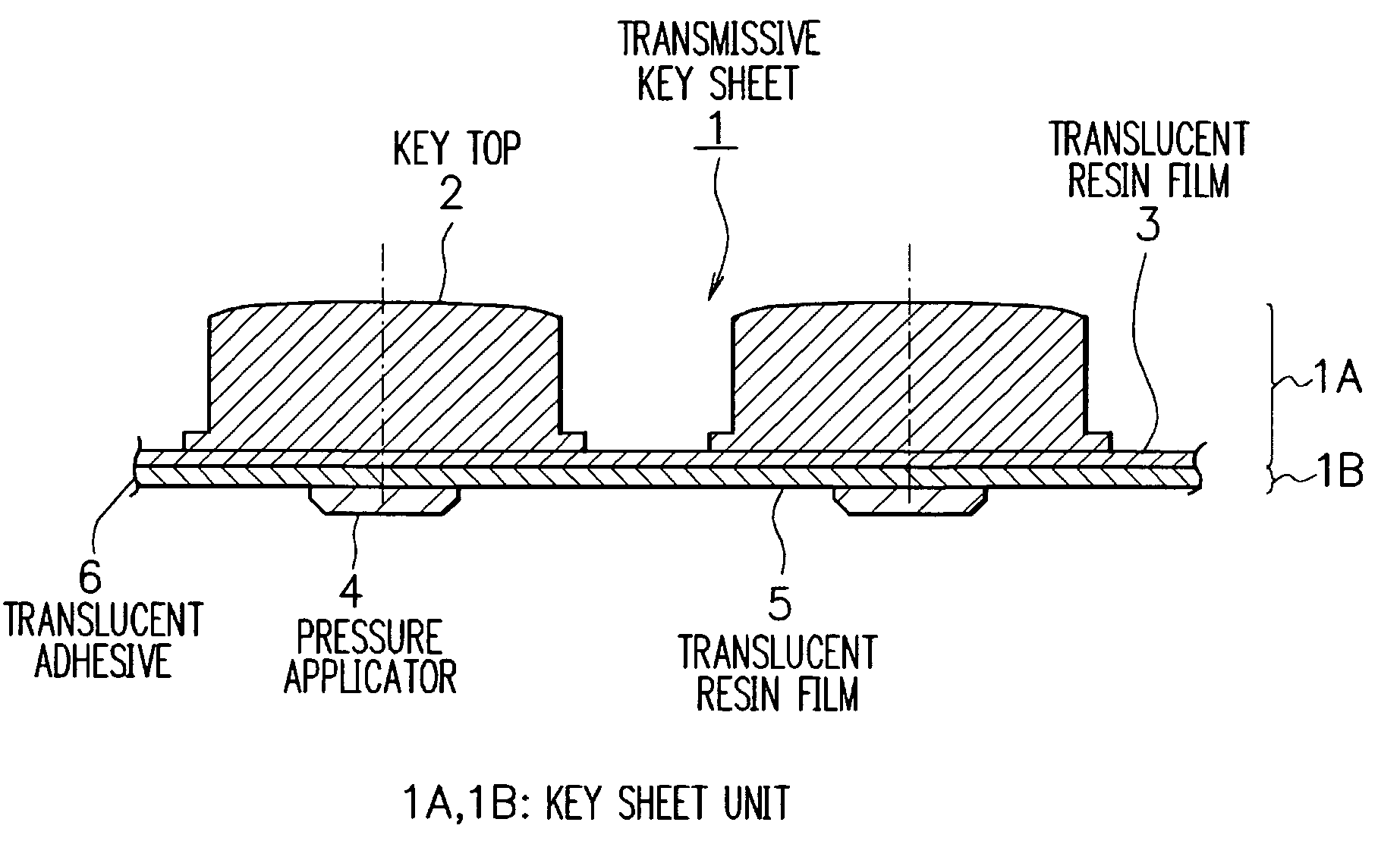
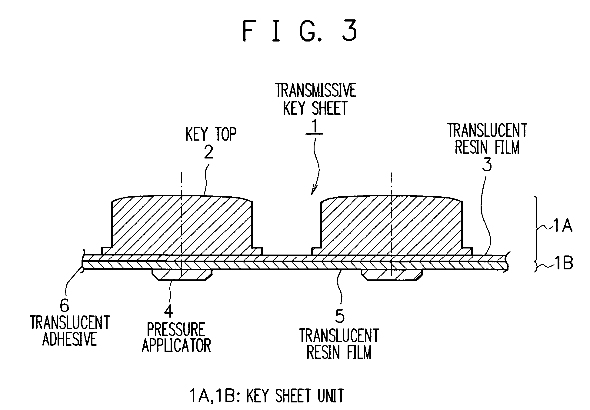
[0059] Referring to FIG. 3, a transmissive key sheet 1 of the first embodiment comprises a key sheet unit 1A (first key sheet unit) and a key sheet unit 1B (second key sheet unit) bonded together with a translucent adhesive 6.

[0060] The key sheet unit 1A includes a translucent resin film 3 and key tops or keycaps 2 made of translucent resin. The key tops 2 are molded integral with the translucent resin film 3. Similarly, the key sheet unit 1B includes a translucent resin film 5 and pressure applicators 4 made of translucent resin. The pressure applicators 4 are molded integral with the translucent resin film 5. PET (polyethylene terephthalate) or the like may be used for the translucent resin film. Besides, examples of the translucent resin include polycarbonate resin, transparent acrylic resin, transparent ABS (acrylonitrile-butadiene-styrene) resin, and PMMA (polymethylmethacrylate).

[0061] Incidentally, in the first and the following embodiments, the translucent resin film may be...

second embodiment

[0075] As shown in FIG. 9, a key sheet unit 1C of the second embodiment includes the translucent resin film 5, to the side of which opposite the pressure applicators 4 arranged at equally spaced intervals is applied light shielding material 22 in such a manner as to avoid portions corresponding to the pressure applicators 4. The light shielding material 22 has a black color or the like with high opacifying power and low reflectance. When the key sheet unit 1C is used instead of the key sheet unit 1B of the input keys 11 shown in FIG. 8, the light shielding material 22 prevents light from leaking out from improper parts. In addition, the light shielding material 22 can cover the portion where the light source 9 is disposed so that the light from the light source 9 is not directly emitted from the key tops 2.

third embodiment

[0076] As can be seen in FIG. 10, a key sheet unit 1D of the third embodiment includes the translucent resin film 5, to the side of which opposite the pressure applicators 4 arranged at equally spaced intervals is applied luminous paint 23 in such a manner as to avoid portions corresponding to the pressure applicators 4. When the key sheet unit 1D is used instead of the key sheet unit 1B of the input keys 11 shown in FIG. 8, the luminous paint 23 accumulates the light from the light source 9. Consequently, the light can be emitted even after the light source is turned off and utilized as an auxiliary lighting.


PUM


Abstract

A transmissive key sheet using translucent resin, which is capable of effective illumination while ensuring the thinness of the entire key sheet as well as suppressing a decrease in light transmission, input keys using the transmissive key sheet, and electronic equipment with the input keys. A transmissive key sheet of input keys comprises a first key sheet unit and a second key sheet unit, the opposite side of the first key sheet unit from key tops and the opposite side of the second key sheet unit from pressure applicators being bonded together with a translucent adhesive. The key tops made of translucent resin are molded integral with a translucent resin film having letters on its under surface to provide the first key sheet unit. The pressure applicators made of translucent resin are molded integral with a translucent resin film to provide the second key sheet unit. The light from a light source on a substrate illuminates keys so that the letters printed on the under surface of the translucent resin film become visible form outside. The pressing of each key top presses a corresponding key switch through the pressure applicator, and the key switch is concavely curved to make a contact with an electrode on the substrate. Thus, key input is provided.

Description

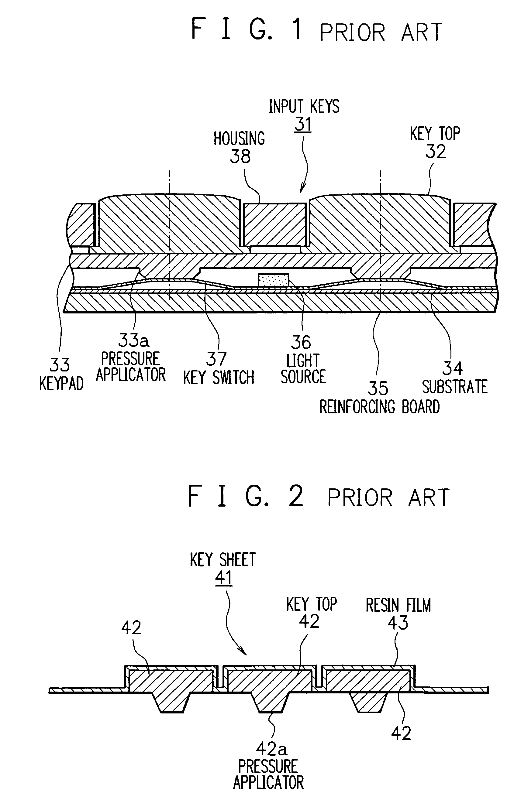
FIELD OF THE INVENTION [0001] The present invention relates to a transmissive key sheet used for input keys having translucent resin key tops on electronic equipment including various types of terminal equipment or mobile communication equipment such as cellular phones and automobile phones, input keys using the transmissive key sheet, and electronic equipment with the input keys. BACKGROUND OF THE INVENTION [0002] It has been well known to use key tops made of translucent resin for input keys or buttons of the input unit of electronic equipment including various types of terminal equipment or mobile communication equipment. [0003] There are two types of such input keys having translucent resin key tops. Input keys of the first type have pressure applicators made of silicon rubber, while those of the other type have key tops integrated with a film as disclosed in Japanese Patent Application laid open No. 2003-217396. [0004]FIG. 1 is a cross section diagram showing conventional input...

Claims


Application Information

Patent Timeline
IPC IPC(8): H01H13/70
CPCH01H13/83H01H2205/004H01H2205/032H01H2219/008H01H2219/03H01H2223/038H01H2219/06H01H2221/006H01H2221/05H01H2221/07H01H2223/034H01H2219/036
Inventor OOSAWA, KAZUO
Owner LENOVO INNOVATIONS LTD HONG KONG
Learn More