
Wafer holder and semiconductor manufacturing apparatus

Inactive Publication Date: 2005-08-04
SUMITOMO ELECTRIC IND LTD
View PDF8 Cites 24 Cited by
  • Summary
  • Abstract
  • Description
  • Claims
  • Application Information

AI Technical Summary

Benefits of technology

[0009] An object of the present invention, in view of such circumstances to date, is to make available a wafer holder in which when the ceramic susceptor therein is in the process of heating, thermal-stress damage to the plurality of tubular pieces and / or columnar pieces affixed to the susceptor can be prevented, and to make available a high-reliability semiconductor manufacturing apparatus utilizing the wafer holder.

Problems solved by technology

H04-78138, the columnar support part itself in order to support the ceramic susceptor ends up being of relatively large heat capacity, wherein a drawback has been that consequently the amount of heat escaping from the ceramic susceptor is large, spoiling the temperature uniformity of the wafer-heating face.
H05-9740, the fact that a plurality of tubular pieces is joined fast to the ceramic susceptor has meant that the stress acting on the tubular pieces during heating processes is great, such that the danger has been that in worst-case scenarios the tubular pieces have been destroyed.
Under these circumstances, in some cases the difference in extent of thermal expansion between the ceramic susceptor and the reaction chamber has been so significant that the stress acting on the tubular pieces grows large enough to damage them.
Because accompanying this transition has been a scaling-up of the ceramic susceptors that heat the wafers, thermal stress acting on the tubular pieces while the ceramic susceptors are heating has grown greater, which has made damage to the affixed tubular pieces all the more likely to occur.
Consequently, because the number of hollow tubular pieces that house these components has also increased, and because in some instances solid columnar pieces are installed on susceptors, the risk that the tubular pieces and columnar pieces will be damaged has also grown all the greater.

Method used


Image

  • Wafer holder and semiconductor manufacturing apparatus
  • Wafer holder and semiconductor manufacturing apparatus
  • Wafer holder and semiconductor manufacturing apparatus

Examples


embodiments

Embodiment One

[0097] Slurries were prepared by putting a predetermined amount of sintering additive in the ceramic powders set forth in Table I below, furthermore adding a solvent or the like and blending the mixture together with a ball mill. Granules were prepared from the slurry by spray-drying it, and the obtained granules were press-molded using dies of predetermined form. The molded objects thus produced were degreased and then sintered at respective predetermined temperatures into sintered ceramic compacts. The thermal expansion coefficient and thermal conductivity of each of the sintered ceramic compacts obtained were measured, and together are set forth in Table I.

TABLE ITherm.ThermalSusceptor chiefSintering additiveexp. coeff.conductivitySamplecomponent(add. amt.)(×10−6 / K)(W / mK)1Aluminum nitride—4.51102Aluminum nitrideY2O3 (0.05%)4.51503Aluminum nitrideY2O3 (0.5%)4.51804Aluminum nitrideY2O3 (1.0%)4.51805Aluminum nitrideY2O3 (5.0%)4.51706Aluminum nitrideEu2O3 (0.5%)4.518...

embodiment two

[0144] The Sample 3-1 wafer holder employed in Embodiment 1 was readied. To this a reflection plate made of stainless steel was attached, and with the temperature of the ceramic susceptor raised to 500° C. the susceptor power consumption was measured. Holes 12 mm in diameter were drilled in the reflection plate so as to allow the tubular pieces and / or support pieces to pass through. Power-consumption measurements were also made at different installment separations between the reflection plate and the ceramic susceptor. The stainless steel plate therein was of 0.5 mm thickness, 330 mm diameter, and Ra=0.05 μm microroughness. The results are set forth in the following Table XLVI.

TABLE XLVIHeater-to-reflection plate separation (mm)Power consumption (W)None12001585030900501050701150901200

[0145] In addition, power consumption was likewise measured with the position of the reflection plate being fixed at 15 mm from the ceramic susceptor, and with the microroughness of the reflection pla...

embodiment three

[0146] One end of tubular pieces and support pieces made of mullite, similar to those of Embodiment 1, were by glass bonding attached to the aluminum nitride susceptor employed in Embodiment 1. In doing so, the parallelism was varied by polishing the tubular-piece and support-piece end faces for the susceptor bonding face to change the angle of their attachment to the susceptor. The other ends of the tubular pieces and support pieces were then mounted into a reaction chamber made of aluminum, and the reaction chamber interior was pumped down to assay its helium leak rate. The results are set forth in Table XLVIII. Here, the microroughness in the vicinity of the O-ring abutment area on the mullite tubular pieces and support pieces was Ra≦0.3 μm in every case, and as a result of observing the surface under an optical microscope, that there were no defects exceeding 0.05 mm was verified.

TABLE XLVIIITubular-piece / support-piece parallelism(mm)Helium leak rate (Pam3 / s)1.5Damaged fitting...


PUM

PropertyMeasurementUnit
Lengthaaaaaaaaaa
Lengthaaaaaaaaaa
Lengthaaaaaaaaaa

Abstract

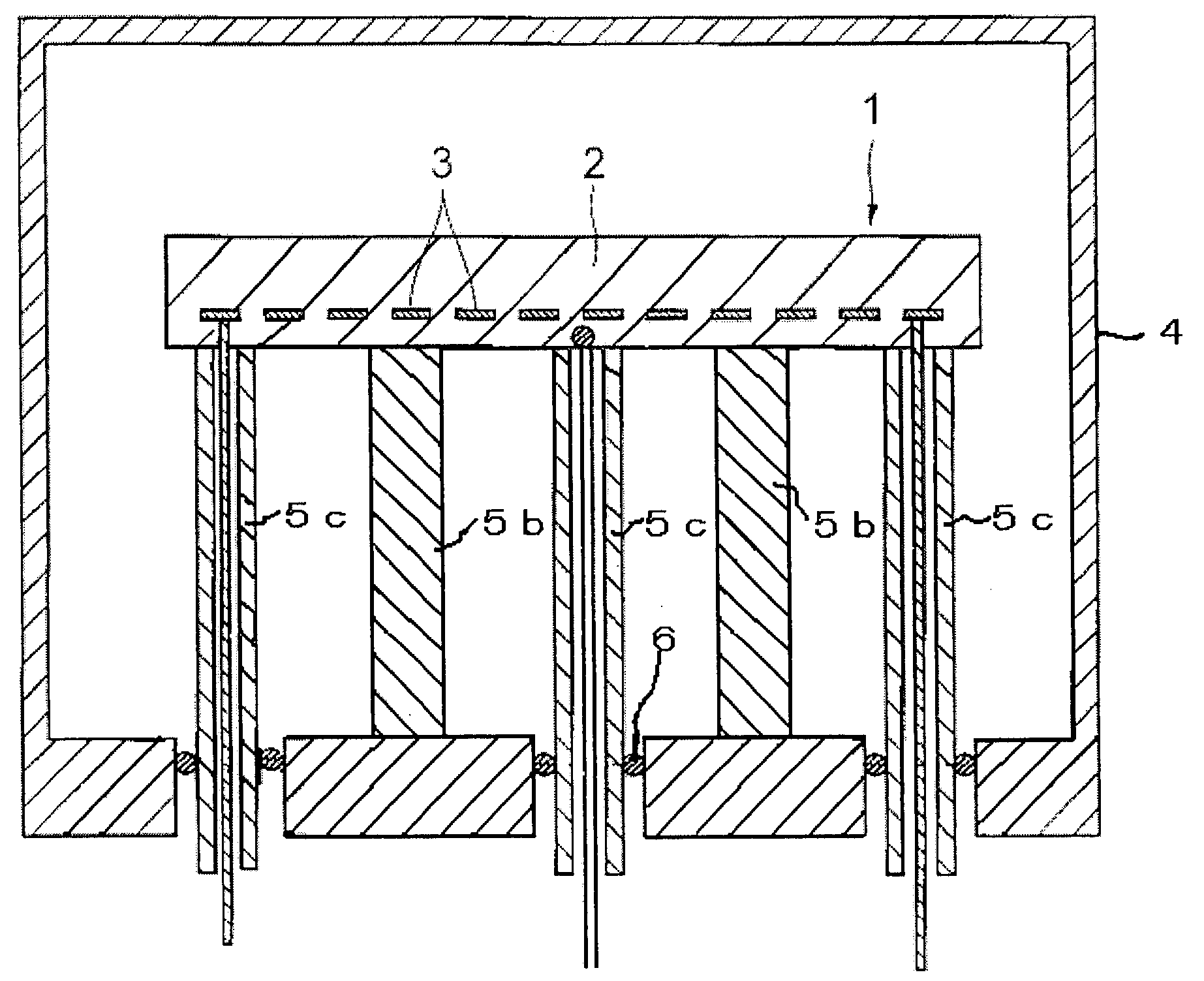
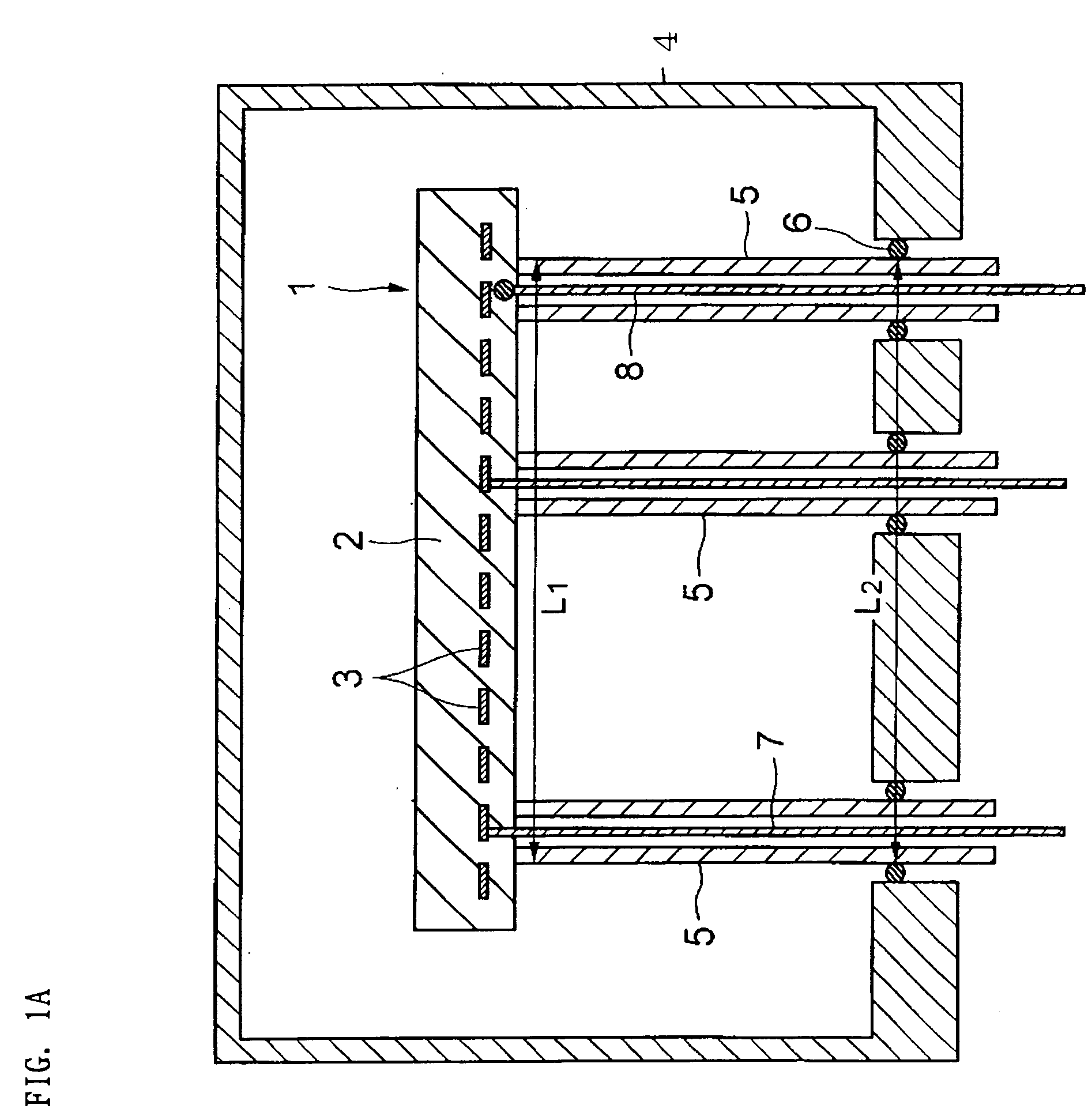
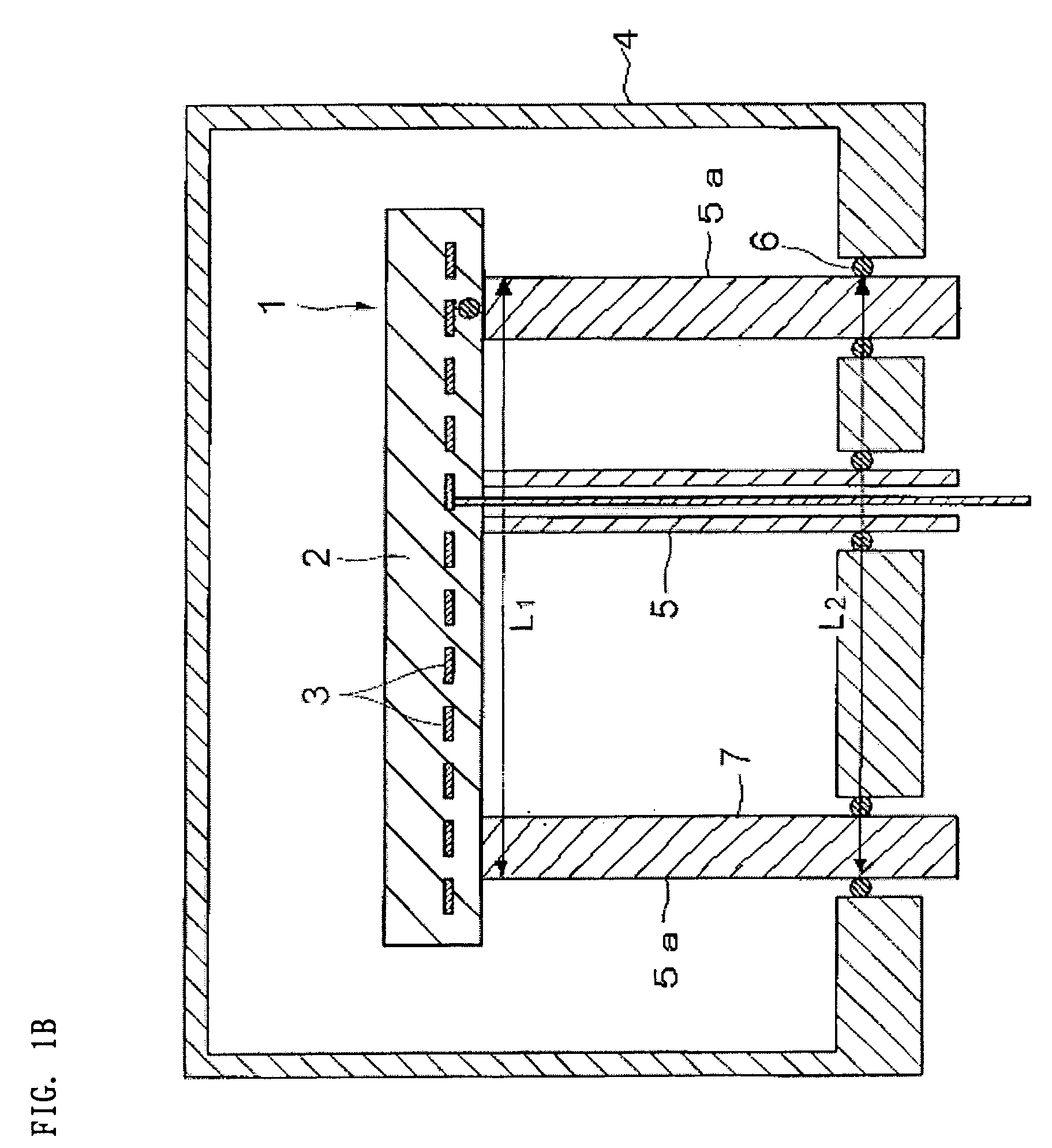
A wafer holder furnished with a plurality of anchored tubular pieces and / or anchored support pieces affixed to the holder's ceramic susceptor and in which damage to the anchored tubular pieces due to thermal stress during heating operations is prevented, and a high-reliability semiconductor manufacturing apparatus utilizing the wafer holder are made available. One end of at least two of the anchored tubular pieces (5) and / or anchored support pieces is affixed to the ceramic susceptor (2) and the other end is fixed in the reaction chamber (4), wherein letting the highest temperature the ceramic susceptor (2) attains be T1, the thermal expansion coefficient of the ceramic susceptor (2) be α1, the highest temperature the reaction chamber (4) attains be T2, the thermal expansion coefficient of the reaction chamber (4) be α2, the longest inter-piece distance on the ceramic susceptor (2) among the plurality of anchored tubular pieces (5) and / or anchored support pieces at normal temperature be L1, and the longest inter-piece distance on the reaction chamber (4) among the plurality of anchored tubular pieces (5) and / or anchored support pieces at normal temperature be L2, then the relational formula |(T1×α1×L1)−(T2×α2×L2)|≦0.7 mm is satisfied.

Description

TECHNICAL FIELD [0001] The present invention relates to wafer holders employed in semiconductor manufacturing operations such as plasma-assisted CVD, low-pressure CVD, low-k film baking, plasma etching and dielectric-film CVD, and to semiconductor manufacturing apparatuses furnished with the wafer holders. BACKGROUND ART [0002] A variety of semiconductor manufacturing apparatuses for implementing on semiconductor wafers processes such as film-deposition and etching has been proposed to date. Such semiconductor manufacturing apparatuses are in their reaction chambers provided with wafer holders furnished with a resistive heating element, and carry out various processes on wafers while the wafers are retained and heated on the wafer holders. [0003] A semiconductor wafer-heating device proposed in Japanese Unexamined Pat. App. Pub. No. H04-78138, for example, includes: a heater part made of ceramic, in which a resistive heating element is embedded, and that is provided with a wafer-hea...

Claims


Application Information

Patent Timeline
IPC IPC(8): H01L21/00H01L21/687H05B3/14
CPCH01L21/67103H05B3/143H01L21/68792H01L21/02
Inventor NATSUHARA, MASUHIRONAKATA, HIROHIKOKUIBIRA, AKIRAHASHIKURA, MANABU
Owner SUMITOMO ELECTRIC IND LTD
Learn More