Fuel cell system having inlet fuel to more than one and/or recycle to less than all of the fuel fields

a fuel cell and system technology, applied in the field of fuel cell power plants, can solve the problems of high pressure drop, difficult pumping of fuel, and added costs, and achieve the effects of improving fuel utilization, reducing pressure fuel recycling, and improving fuel utilization

Active Publication Date: 2005-07-28
AUDI AG
View PDF2 Cites 44 Cited by
  • Summary
  • Abstract
  • Description
  • Claims
  • Application Information

AI Technical Summary

Benefits of technology

[0006] Objects of the invention include: improved fuel utilization in fuel cell power plants; lower fuel pressure drop across the fuel flow fields of fuel cell power plants; improved fuel utilization in serial fuel cell fuel flow fields; reduced pressure fuel recycle in fuel cell power plants; and improved fuel handling and utilization in fuel cell power plants.
[0009] According further to the invention, to provide a lower fuel velocity through a first fuel flow field of a fuel cell power plant that feeds the fuel to a next fuel flow field in a series of fuel flow fields, some of the inlet fuel is bypassed around the first flow field in the series and applied directly to the fuel inlet of an additional fuel flow field in the series. Bypassing a portion of the fuel around the first flow field is beneficial because it reduces the pressure drop through the first flow field as a result of the reduced flow. The reduced flow also results in less dryout of the electrolyte at the entrance to the first flow field. This is particularly important in extending the life of the electrolyte where the electrolyte is a proton exchange membrane. In one example, two fuel cell stacks are connected in series, the second stack in the series receiving fuel both from the first stack in the series and from the fuel supply pipe. In another example, both the first and second stages of a cascaded fuel cell stack receive fuel from the fuel supply pipe. Another example of this aspect of the invention provides fuel from a source directly to the last flow field in the series.

Problems solved by technology

Recycling fuel requires a blower or compressor which adds costs and consumes parasitic power.
In the case of pure hydrogen systems, in contrast with reformate, the fuel is difficult to pump due to the low density of hydrogen.
Such systems can achieve overall system fuel utilization on the order of 99% without using a fuel recycle loop, but such systems present other problems.
These problems include a high pressure drop across the fuel flow fields; a risk of local fuel starvation, especially in the last of the fuel flow fields, since the hydrogen is diluted by inert gases such as nitrogen that migrates through the electrolyte; and difficulty in startup or shut down of the fuel cell system because of the problem of introducing fuel rapidly throughout the system, particularly on startup.

Method used


Image

  • Fuel cell system having inlet fuel to more than one and/or recycle to less than all of the fuel fields
  • Fuel cell system having inlet fuel to more than one and/or recycle to less than all of the fuel fields
  • Fuel cell system having inlet fuel to more than one and/or recycle to less than all of the fuel fields

Examples


Embodiment Construction

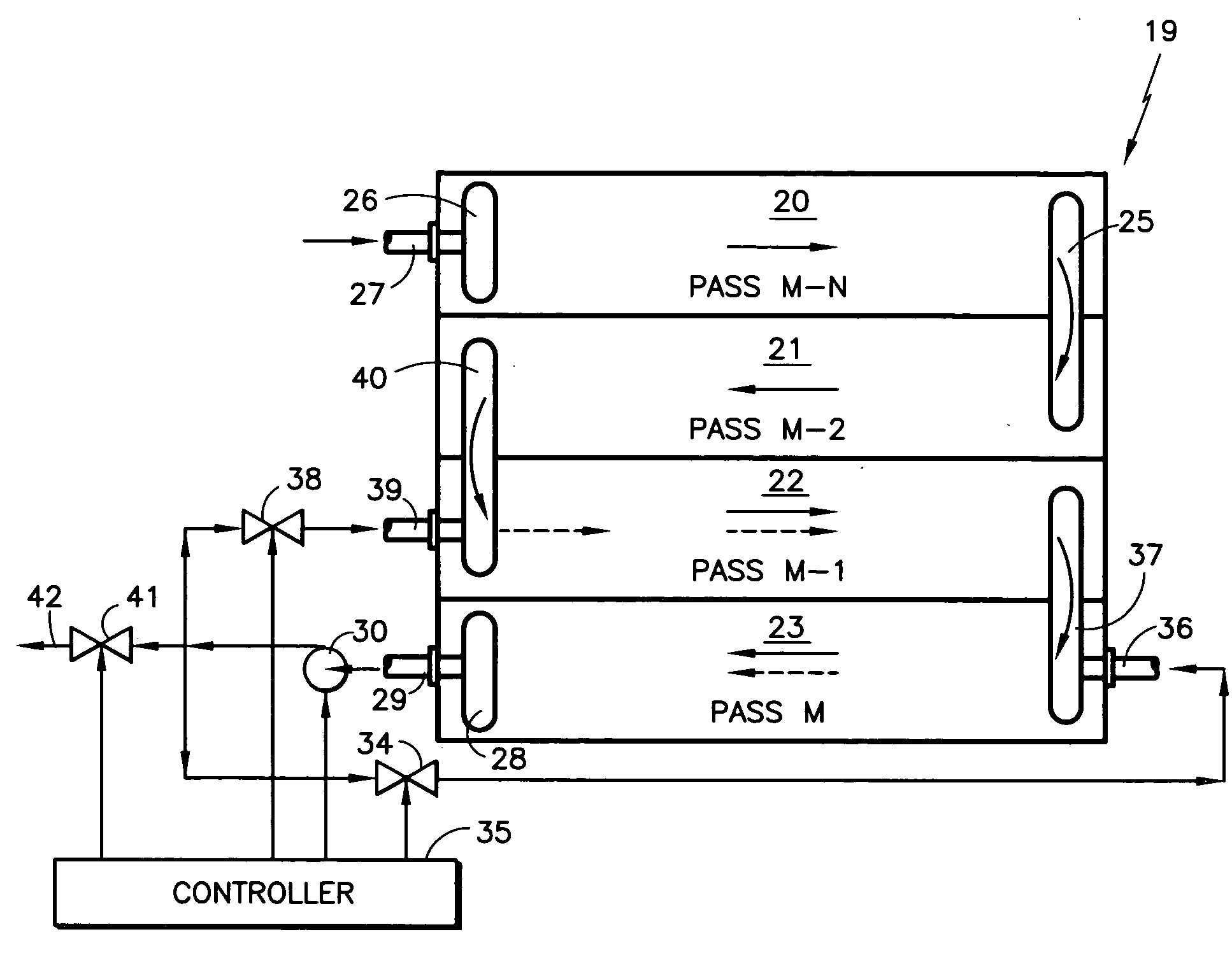
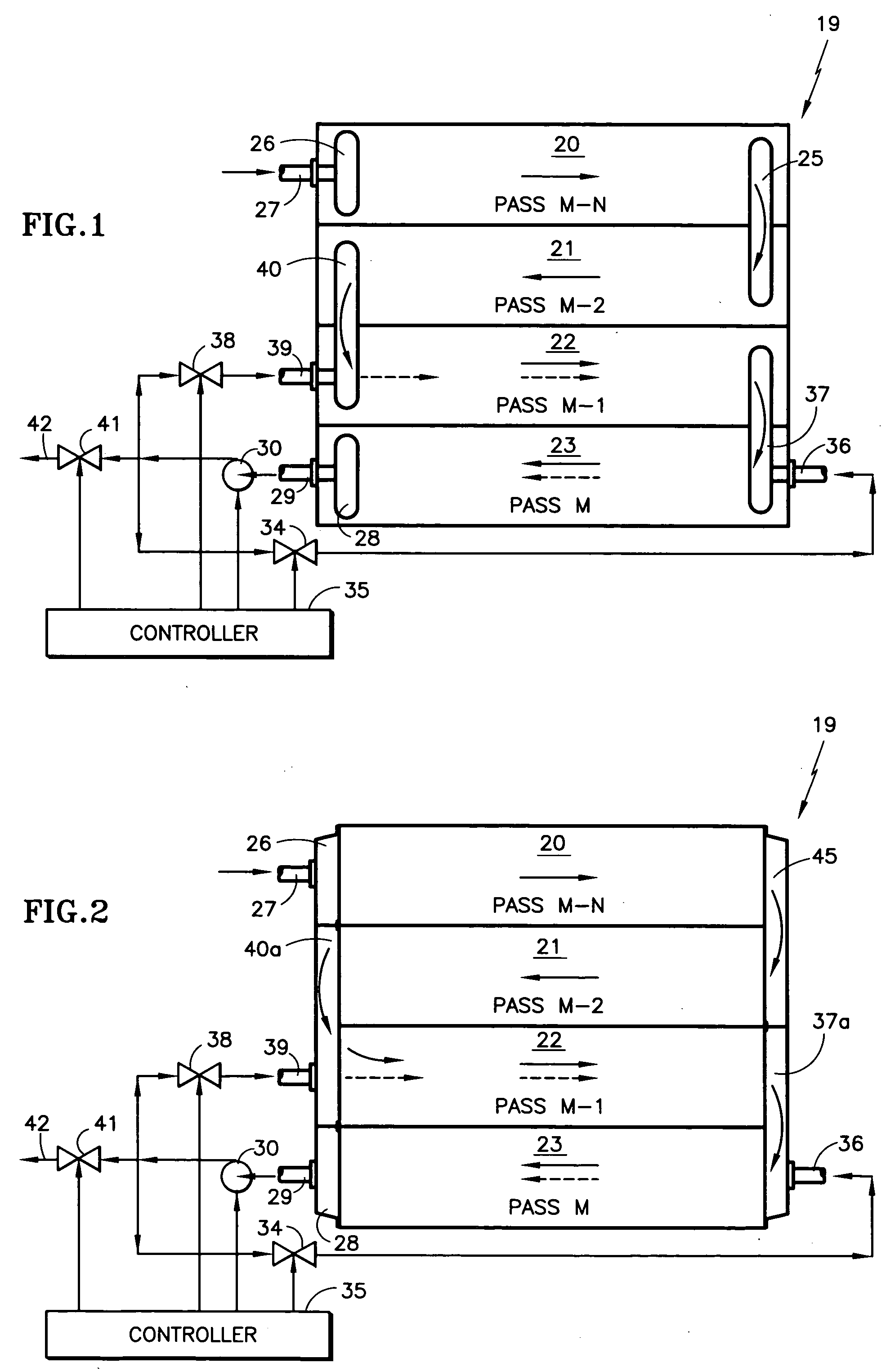
[0029] Referring to FIG. 1, a fuel cell power plant 19 comprises a plurality of fuel cells (only one is shown), each having fuel flow channels arranged in a series of M fuel flow fields 20-23 which comprise pass M−N through pass M, the fuel flow channels of each pass 20-22 except the last pass 23 being fed to the next pass 21-23 in the series. The transition 25 between flow field 20 and flow field 21 is an internal turn manifold. Fuel is received at an internal fuel inlet manifold 26 from a fuel supply pipe 27, and the exhaust of the fuel cell stack 19 passes through an internal fuel exit manifold 28 and pipe 29 to a fuel recycle impeller 30. The output of the fuel recycle impeller 30 is fed through a first valve 34 in response to a controller 35 to a bypass inlet pipe 36 and internal manifold 37 to the last pass 23 of the fuel cell stack, as well as through a valve 38 and a bypass inlet pipe 39 and internal manifold 40 to the −1 pass 22 of the fuel cell stack. Some portion of the e...


PUM


Abstract

Fuel cell power plants (19, 47, 60, 86, 102, 112, 121) include recycle fuel from a fuel exit (29) of the last fuel flow field (23, 52, 64, 89) of a series of flow fields (20-23; 49-52; 61-64; 87-89) labeled M−N through M, applied either to the Mth flow fields or both the Mth and the (M−1)th flow fields. The fuel recycle impeller is a blower (30), a turbocompressor (30a) driven by an air exhaust, an ejector (30b) or an electrochemical hydrogen pump (30c). Fuel from a source (77) may be applied both to the first fuel flow field (87) and an additional fuel flow field (88, 74, 75, 89) of a series of flow fields to reduce pressure drop and flow rate requirements in the first of the series of flow fields and assure more fuel in the additional fuel flow field. Flow to the additional fuel flow field may be controlled by voltage (126) in such field or fuel content (128) of its exhaust. Transient fuel volume is provided by a tank (125).

Description

TECHNICAL FIELD [0001] This invention relates to a fuel cell power plant in which: fuel exhausting from the fuel cell power plant is returned by a fuel recycle loop to some, but less than all, of the fuel flow fields within the fuel cell power plant; fuel is fed to at least two flow fields; and recycle fuel is impelled by a blower, an electrochemical hydrogen pump, or an ejector (eductor). BACKGROUND ART [0002] In order to achieve very high fuel utilization in a proton exchange membrane fuel cell power plant, such as on the order of 99%, while avoiding fuel starvation in any part of the fuel cell power plant, a fuel recycle loop is commonly employed. Such a recycle loop receives the fuel exhaust from the fuel cell power plant, and returns it to the fuel inlet of the fuel cell power plant, utilizing a pump of some sort to restore the pressure of the recycled fuel to a pressure substantially the same as the pressure of the fresh, inlet fuel. The use of a fuel recycle loop allows the f...

Claims


Application Information

Patent Timeline
IPC IPC(8): H01M8/04H01M8/24
CPCH01M8/04089H01M8/04097Y02E60/50H01M8/2465H01M8/249H01M8/04201H01M8/2483H01M8/04H01M8/2418H01M8/2484
Inventor MARGIOTT, PAUL R.PERRY, MICHAEL L.REISER, CARL A.VUKOVINSKY, MICHAEL L.
Owner AUDI AG
Why Eureka
Try Eureka