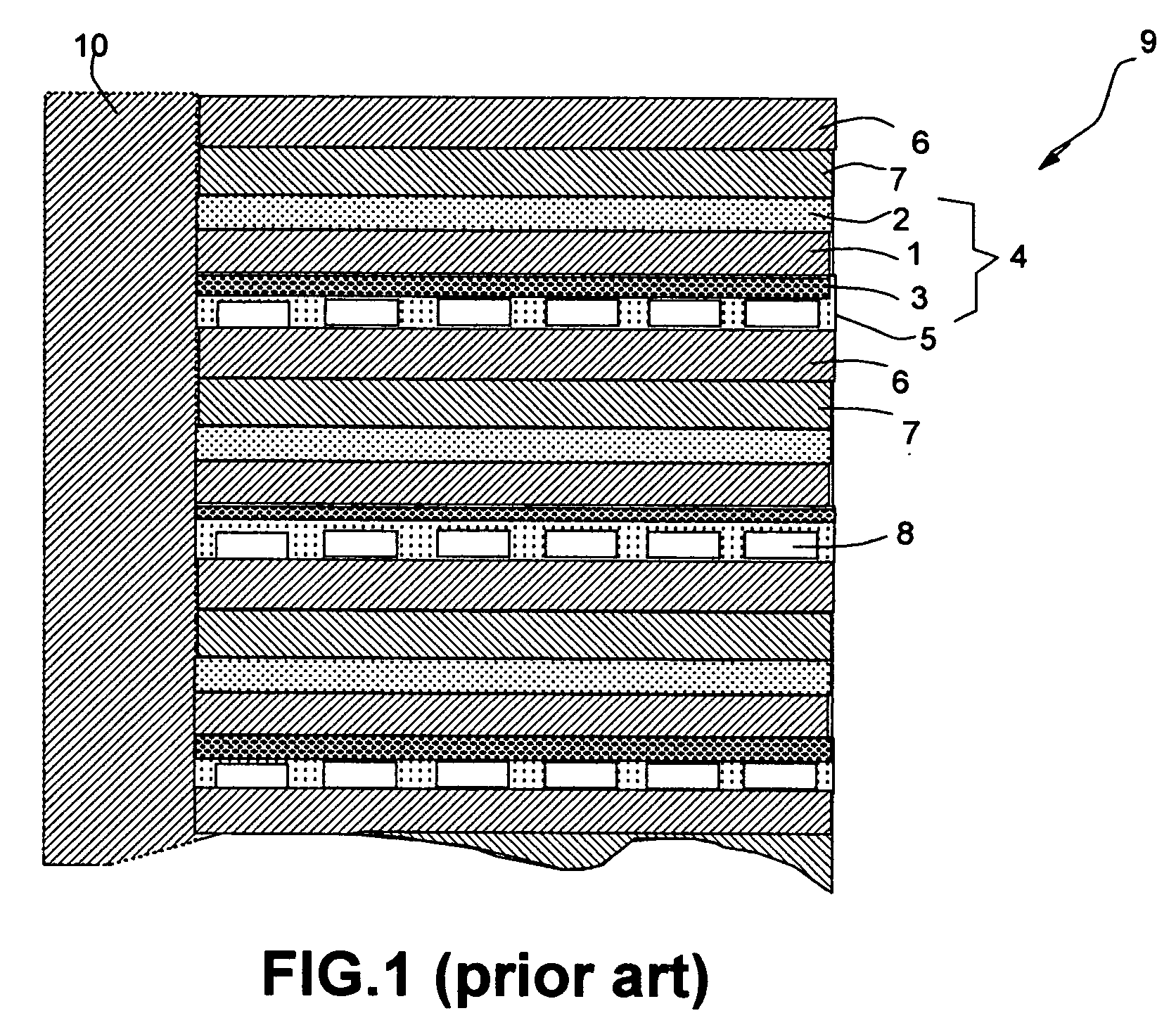
Local vapor fuel cell

Inactive Publication Date: 2005-07-28
NANOTEK INSTR
View PDF4 Cites 15 Cited by
  • Summary
  • Abstract
  • Description
  • Claims
  • Application Information

AI Technical Summary

Benefits of technology

[0015] (2) Since the heat is generated locally to vaporize the liquid fuel near the anode, there is very little heat loss to the outside environment. By contrast, the current direct methanol fuel cell of a direct vapor feed type requires a vaporizer and a blower to deliver the vaporized fuel from the vaporizer to the fuel cell body through a pipe. This procedure is prone to heat energy loss. Besides, the combined vaporizer-blower-pipe makes the fuel cell bulky and heavy.
[0016] (3) The vaporous fuel at a higher temperature means a faster and more efficient catalytic reaction at the anode catalyst site. This reaction condition promotes essentially full conversion of the fuel into the desired electrons and protons, thereby minimizing methanol crossover from the anode to the cathode side through the electrolyte. A reduced methanol crossover implies not only a higher electro-oxidation of methanol-water fuel at the anode, but also less methanol “poisoning” of the cathode catalyst which allows better contacts between oxygen and the cathode catalysts.
[0017] (4) The liquid fuel feeding via capillarity pressure-driven diffusion of liquid fuel through the anode makes it possible to have a highly compact fuel cell assembly due to the fact that no liquid fuel pump or vapor fuel blower is needed in the LVFC.
[0018] The above extrinsically controlled LVFC, in practice, needs a temperature sensor, a heating element, and a simple temperature-controlling circuit. The intrinsically controlled LVFC has the following added advantage:

Problems solved by technology

This procedure is prone to heat energy loss.
Besides, the combined vaporizer-blower-pipe makes the fuel cell bulky and heavy.

Method used


Image

  • Local vapor fuel cell
  • Local vapor fuel cell
  • Local vapor fuel cell

Examples


example 1

[0043] A fuel cell was prepared as follows: Graphite flakes were subjected to a ball-milling treatment to obtain fine particles of several microns in size. These fine particles were mixed with a phenolic resin to obtain a slurry mixture. Chopped carbon fibers were then mixed with the slurry mixture to prepare a composite, which was then molded at a temperature of 250° C. for one hour with a hot press and then partially carbonized first at 350° C. and then at 600° C. for approximately two hours. These treatments lead to the formation of a thin, highly porous carbon structure having an average pore diameter of 60 μm and a porosity of approximately 65%. A sheet of this carbon composite structure was coated on one side with a Pt—Ru catalyst to give an anode of 32 mm×32 mm in dimensions. A carbon cloth was coated with a platinum black catalyst to give a cathode also of 32 mm×32 mm. A polymer electrolyte membrane, poly(perfluorosulfonic acid) ionomer, was held between the anode and the ca...

example 2

[0046] A series of fuel cells were prepared and operated in the same way as in Example 1, with the exception that a thin copper wire was introduced into and out of the anode at a location very close to the polymer electrolyte layer (and, hence, close to the catalyst layer). A desired amount of current was fed into this zone to vary the fuel temperature between approximately 64° C. (the boiling point of methanol) and 130° C. (30° above 100° C., the boiling point of water) while the exterior temperature was maintained at a relatively low level by blowing a cool air to the fuel cell while in operation. It was found that, in general, the higher the reaction temperature, the more stable the voltage was. A higher local temperature near the catalyst phase implies not only a higher vapor content, but also a higher electrolytic reaction rate at the anode (Reaction 1). Both factors are in favor of a more stable voltage response as a function of current by way of an increased reactivity (faste...


PUM


Abstract

A local vapor fuel cell, comprising (A) an anode receiving a liquid fuel from a liquid fuel source substantially through diffusion; (B) an electrolyte plate having a first surface adjacent to the anode; and (C) a cathode adjacent to a second surface of the electrolyte plate and opposite to the anode. The anode is provided with a heating environment to at least partially vaporize the liquid fuel inside the anode and the anode further comprises a catalyst phase to ionize the fuel in a vapor or vapor-liquid mixture form to produce protons. The electro-catalytic reaction at the anode is more efficient with a vapor phase or vapor-liquid mixture than with liquid fuel alone. The invented fuel cell is compact in size and light in weight and, hence, is particularly useful for powering small microelectronic devices such as a notebook computer, a personal digital assistant, a mobile phone, and a digital camera.

Description

FIELD OF THE INVENTION [0001] This invention relates to a fuel cell operating on a hydrogen-rich organic fuel that is initially in a liquid form directly fed via diffusion into the anode; but the fuel turns into a vapor form when it comes in contact with the catalyst phase in the anode. The diffusion process is preferably driven by a capillarity force without using a liquid delivery pump. The invention specifically relates to a local vapor fuel cell (LVFC) such as a methanol vapor fuel cell (MVFC) or ethanol vapor fuel cell (EVFC). BACKGROUND OF THE INVENTION [0002] A fuel cell is a device which converts the chemical energy into electricity. A fuel cell differs from a battery in that the fuel and oxidant of a fuel cell are supplied from sources that are external to the cell, which can generate power as long as the fuel and oxidant are supplied. A particularly useful fuel cell for powering portable electronic devices is a direct methanol fuel cell (DMFC) in which the fuel is a liquid...

Claims


Application Information

Patent Timeline
IPC IPC(8): H01M8/04H01M8/24
CPCH01M8/0258H01M8/04007Y02E60/50H01M8/2455H01M8/04186H01M8/0267
Inventor YANG, LAIXIAHUANG, WEN C.
Owner NANOTEK INSTR
Why Eureka
Try Eureka