Variable displacement compressor

Active Publication Date: 2005-07-28
SANDEN CORP
View PDF26 Cites 9 Cited by
  • Summary
  • Abstract
  • Description
  • Claims
  • Application Information

AI Technical Summary

Benefits of technology

[0006] Accordingly, an object of the present invention is to provide a variable displacement compressor which can reduce a sliding resistance accompanying with the movement of a valve element of a displacement control valve, thereby controlling displacement for discharge smoothly.
[0007] Another object of the present invention is to provide a structure wherein, in addition to the above-described structure for reducing the sliding resistance, it is possible to form a fixed orifice, which has been formed at a cylinder block side or the vicinity thereof and provided at a position in a pressure relief passageway communicating from a crank chamber to a suction chamber, in a displacement control valve, thereby simplifying the processing, in particular, simplifying the processing of the cylinder block side.
[0012] Moreover, it is preferred to employ a structure wherein the solenoid comprises an electromagnetic coil excited for generating an electromagnetic force, a fixed iron core for generating a magnetic force by excitation of the electromagnetic coil, and a plunger attracted and moved to fixed iron core side by the magnetic force of the fixed iron core, and in this structure, the other end of the valve element is fixed to the plunger, the plunger is held slidably in an axial direction of the valve element, and a gap is defined between the fixed iron core and the valve element for forming a non-contact structure which does not give a sliding resistance relative to a movement of the valve element in its axial direction. By this, the sliding parts present in the respective portions of the fixed iron core and the plunger in the aforementioned conventional structure may become only a sliding part of the plunger. Therefore, in this structure, the number of the conventional four sliding parts becomes totally two, namely, the sliding parts in the axially extending portion of the valve element including the plunger become only two sliding parts at both end portions (two-point suspension), and even from the viewpoint of the principle of supporting mechanism, a smooth operation of the movement of the valve element may be assured.
[0013] Thus, in the variable displacement compressor according to the present invention, since a non-contact gap structure is formed at a portion of the partition wall and generation of a sliding resistance is prevented at this portion, and the number of sliding parts may be reduced also in the solenoid side, the sliding resistance accompanying with the movement of the valve element may be greatly reduced, and a stable and smooth control of displacement for discharge may be achieved by the smooth operation of the valve element.
[0014] Further, because the gap in the partition wall may be formed as the fixed orifice, it becomes unnecessary to provide the fixed orifice at another portion of the compressor, thereby simplifying the processing of the cylinder block and its vicinity portion and reducing the cost as a whole.

Problems solved by technology

Moreover, because four sliding parts are arranged in the same axial direction, it may be difficult to maintain the respective sliding parts accurately at respective predetermined positional relationships without shifting, and also from this point of view, there is a fear to enlarge the sliding resistance.
If the movement of valve element 118 is deteriorated by such a sliding resistance, a smooth control of displacement for discharge of the variable displacement compressor may be damaged.

Method used


Image

  • Variable displacement compressor
  • Variable displacement compressor
  • Variable displacement compressor

Examples


Embodiment Construction

[0019] Hereinafter, desirable embodiments of the present invention will be explained referring to figures.

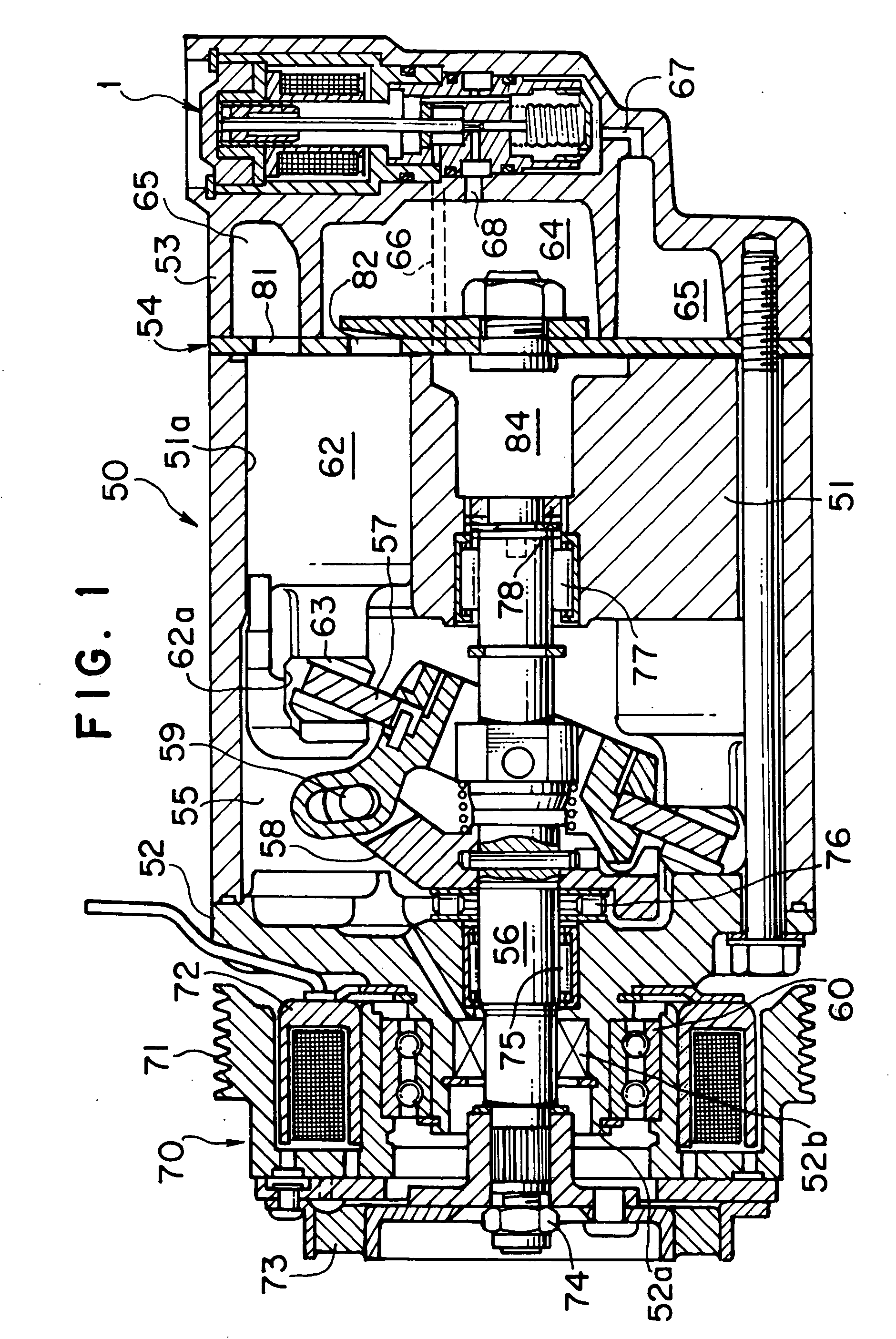
[0020] In FIG. 1, a variable displacement compressor 50 has a cylinder block 51 with a plurality of cylinder bores 51a, a front housing 52 provided at one end of cylinder block 51, and a rear housing 53 provided to cylinder block 51 via a valve plate device 54. A compressor main shaft 56 is provided as a drive shaft across a crank chamber 55 formed by cylinder block 51 and front housing 52, and an inclined plate 57 is disposed around a central portion of the compressor main shaft. Inclined plate 57 connects a rotor 58 fixed to compressor main shaft 56 and a connecting portion 59.

[0021] One end of compressor main shaft 56 extends to an outside through a boss 52a protruded toward an outside of front housing 52, and an electromagnetic clutch 70 is provided around the boss 52a via a bearing 60. Electromagnetic clutch 70 comprises a rotor 71 provided around boss 52a, a magnet unit ...


PUM


Abstract

A variable displacement compressor capable of controlling a piston stroke by openably controlling a displacement control valve to regulate a pressure in a crank chamber, comprising the displacement control valve disposed in a passageway from a discharge chamber to the crank chamber, and a fixed orifice provided in a passageway from the crank chamber to a suction chamber, the displacement control valve further comprising a pressure sensing member for the pressure in the suction chamber or the crank chamber, a valve element having a valve part opened and closed in response to the operation of the pressure sensing member, a valve chamber for disposing the valve part therein and allowing the pressure in the crank chamber to act therein, a partition wall disposed around the valve element, a pressure chamber partitioned from the valve chamber by the partition wall and allowing the pressure in the suction chamber to act therein, and a solenoid provided to the other end of the valve element, wherein a flow passage of non-contact structure is formed in the partition wall, and the number of sliding parts is reduced to lower a sliding resistance.

Description

TECHNICAL FIELD OF THE INVENTION [0001] The present invention relates to a variable displacement compressor used in an air conditioning system for vehicles, etc., and specifically to a variable displacement compressor capable of allowing a smooth operation of a displacement control valve at a high reliability and capable of simplifying the processing of the compressor as a whole. BACKGROUND ART OF THE INVENTION [0002] As a variable displacement compressor provided in a refrigeration circuit of an air conditioning system for vehicles, etc., a compressor such as one disclosed in JP-A-11-107929 is known. To this variable displacement compressor, in order to control its displacement for discharge, a displacement control valve is provided, in which a control point for a pressure in a suction chamber is decided to be one-to-one relative to an amount of electricity applied to an electromagnetic actuator, and which can maintain the variable displacement compressor forcibly at a minimum disp...

Claims


Application Information

Patent Timeline
IPC IPC(8): F04B27/14F04B49/00F04B27/18
CPCF04B27/1804F04B2027/1813F04B2027/1859F04B2027/1845F04B2027/1854F04B2027/1827
Inventor TAGUCHI, YUKIHIKO
Owner SANDEN CORP
Why Eureka
Try Eureka