Tuner input filter with electronically adjustable center frequency for adapting to antenna characteristic

a technology of center frequency and input filter, which is applied in the direction of continuous tuning, television system, selective content distribution, etc., can solve the problems of incorrect bandwidth base, and inability to provide a good 75 ohm sour

Inactive Publication Date: 2005-07-28
THOMSON LICENSING SA
View PDF12 Cites 14 Cited by
  • Summary
  • Abstract
  • Description
  • Claims
  • Application Information

AI Technical Summary

Benefits of technology

[0014] In one form, there is provided a method for tuning a signal channel comprising the steps of: (a) selecting a signal channel to be tuned; (b) tuning the selected signal channel by applying a control signal to an electronically tunable input filter of the signal tuner, the control signal causing a center frequency of the electronically tunable input filter to correspond to an expected frequency of the signal channel to be tuned; (c) providing an initial control signal to the electronically adjust...

Problems solved by technology

Many types of television antennas, particularly those of the indoor variety such as what are known as “rabbit ears”, are not capable of providing a good 75 ohm source.
The resistive component will, in most cases, cause the input transforming network at the RF filter input to create the incorrect bandwidth base on the loaded Q of the network.
The unknown impedance may cause the RF input circuit's center frequency to shift, result...

Method used


Image

  • Tuner input filter with electronically adjustable center frequency for adapting to antenna characteristic
  • Tuner input filter with electronically adjustable center frequency for adapting to antenna characteristic
  • Tuner input filter with electronically adjustable center frequency for adapting to antenna characteristic

Examples


Embodiment Construction

)

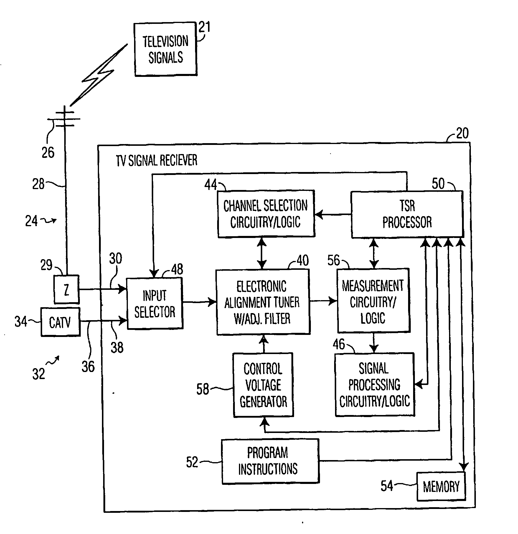
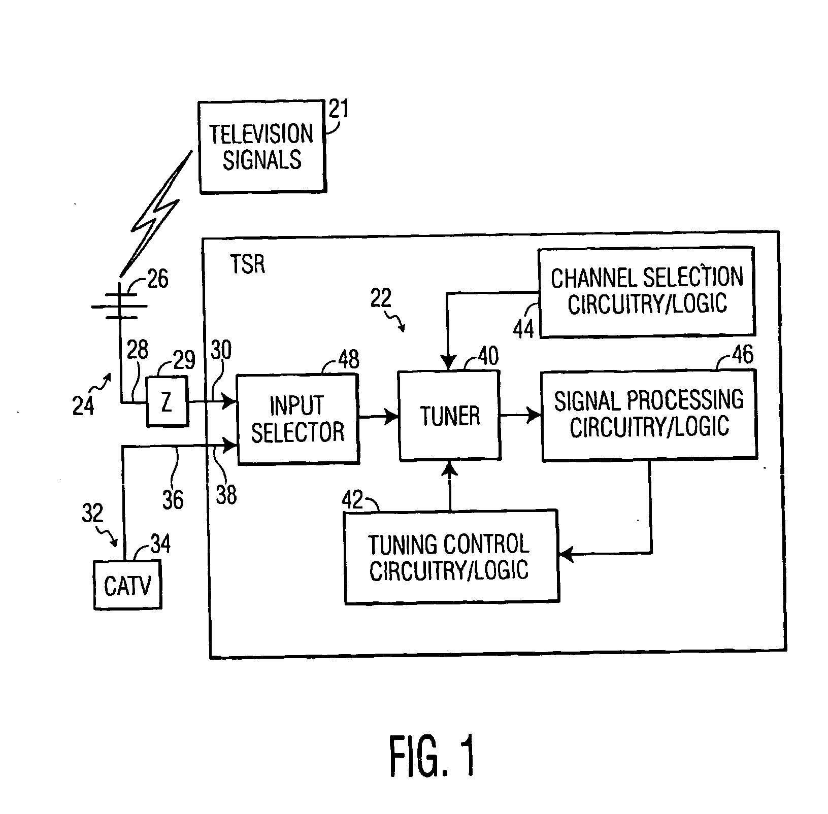
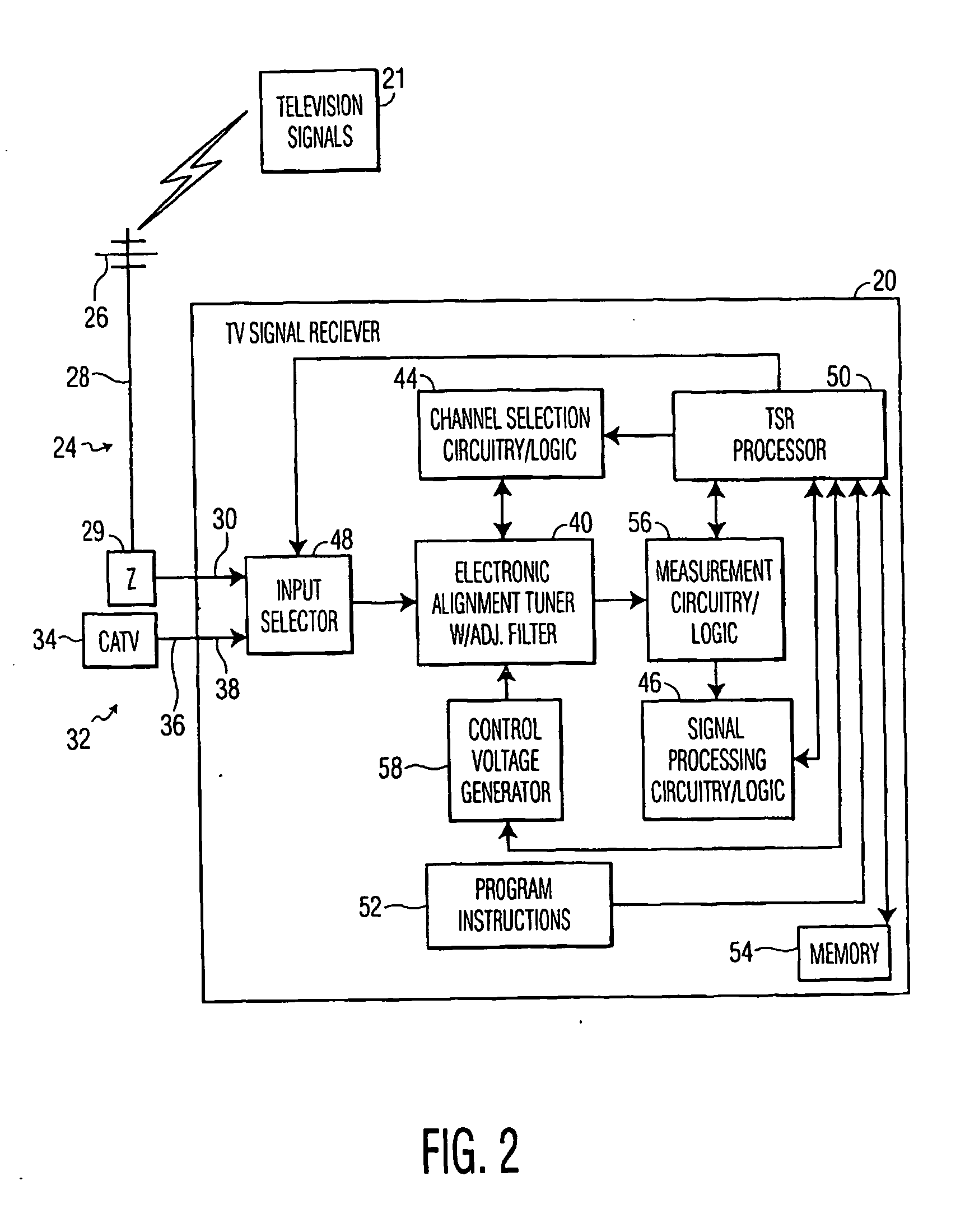
[0026] Referring now to FIG. 1, there is depicted a block diagram of an RF signal receiver 20 to which the subject invention pertains. The RF signal receiver 20 is preferably, but not necessarily, of the type that accepts connection to an antenna of an unknown impedance by the user for RF signal reception rather than utilizing a fixed, known impedance antenna. The RF signal receiver 20 may be, and thus is representative of, any type of RF signal receiver such as a television, radio, VCR, television signal receiver, cellular phone, wireless local area network, or the like, to which a user may attach an antenna and typically an external antenna for receiving the RF signals. In the following description of an exemplary embodiment of the invention, a television receiver is described as a representative example of a system suitable for incorporating principles of the invention. However, the principles discussed herein in the context of a television receiver apply to any form of RF signa...


PUM


Abstract

A system, apparatus and/or method provides frequency response adjustment of an RF input filter of an RF tuner based on impedance of an antenna system that is providing reception of RF signals to the RF tuner. The frequency response adjustment is preferably accomplished dynamically and/or with respect to each frequency tuned. Particularly, the system, method and/or apparatus provides compensation at the RF tuner level for mistuning effects produced on the RF tuner by antenna system impedance presented at the antenna input that is other than a designed for impedance. Frequency response of an RF input filter for the RF tuner is electronically adjustable with an independent or semi-independent control voltage signal based on one or more measured parameters of a tuning frequency. Frequency response adjustment may include adjustment of a center frequency of the RF input filter bandpass frequency range and/or altering the bandpass frequency range of the RF input filter. The subject invention expands the capability of an RF signal receiver, particularly one using at least one electronically adjustable RF filter at the input of an electronic alignment type tuner.

Description

[0001] This U.S. non-provisional patent application claims the benefit of and / or priority to the following three U.S. provisional patent applications, all filed on Apr. 26, 2002 and all commonly assigned: U.S. provisional patent application Ser. No. 60 / 376,099 entitled Tuner Input Filter With Electronically Adjustable Center Frequency For Adapting to Antenna Characteristic, U.S. provisional patent application Ser. No. 60 / 376,127 entitled Tuner RF Input Filter With Integrated Signal Boost Provision, and U.S. provisional patent application Ser. No. 60 / 376,128 entitled Tuner Input Filter With Electronically Adjustable Response For Adapting to Antenna Characteristic. CROSS REFERENCE TO RELATED APPLICATIONS [0002] Cross reference is made to related U.S. Patent application serial number ______ entitled Tuner Input Filter With Electronically Adjustable Response For Adapting To Antenna Characteristic by Michael Anthony Pugel and Kumar Ramaswamy (Attorney Docket Number PU020191) filed on eve...

Claims


Application Information

Patent Timeline
IPC IPC(8): H03J3/22H03J1/00H03J3/18H03J3/20H04B1/18H04N5/50H04N5/52
CPCH03J1/0066H03J3/185H03J3/20H04N21/44209H04N5/50H04N5/52H04N21/4383H03J2200/28H03J1/00
Inventor HALL, EDWARD ALLENGRUBBS, GARY DEANPUGEL, MICHAEL ANTHONYMUTERSPAUGH, MAX WARD
Owner THOMSON LICENSING SA
Why Eureka
Try Eureka