
Ultra short high pressure gradient flow path flow field

Inactive Publication Date: 2005-07-21
GM GLOBAL TECH OPERATIONS LLC
View PDF5 Cites 10 Cited by
  • Summary
  • Abstract
  • Description
  • Claims
  • Application Information

AI Technical Summary

Benefits of technology

[0012] The present invention is directed to a flow field design for achieving stable gas flows in the presence of liquid water, as well as for heightening the oxygen partial pressure in the catalyst layer in order to raise cell performance. The flow field design includes an intake manifold and an exhaust manifold which are configured in two offset planes. A relatively short passage extends from the intake manifold to the exhaust manifold and terminates at a diffusion medium such that fluid communication is provided from the intake manifold through the passage and the diffusion medium to the exhaust manifold. Thus, the present invention may be employed to establish convective, interdigitated-like flow through a diffusion medium in order to raise the oxygen partial pressure at the catalyst layer.

Problems solved by technology

The catalytic particles are typically costly precious metal particles.
As such these MEAs are relatively expensive to manufacture and require certain conditions, including proper water management and humidification and control of catalyst fouling constituents such as carbon monoxide (CO), for effective operation.
The requirement for stable flow (6), is a difficult requirement to meet.
First, it is difficult to determine exactly when stable flow has been achieved because there is more than one condition under which it can be successfully accomplished.
For example, in some cases gas velocity may be sufficiently high such that collection of liquid water is not possible.
In other cases, liquid water may collect and then a pressure build up may occur, causing the liquid water to move out.
In some cases low gas velocity and an inability to build pressure cause unfavorable water removal conditions and an unstable gas flow.
The second reason stable flow is difficult to meet is that in order to satisfy it, other flow field requirements must be compromised.
The following three examples demonstrate the difficulty in designing a flow field that can satisfy all requirements concurrently, including establishing either one of the two possible stable flow conditions needed for consistent water removal.
However, for an averaged-sized active area, the consequence of such a design is a flow field having an unacceptably high overall pressure drop.
Then, with the establishment of many parallel flow paths, removal of liquid water by a pressure build-up is no longer possible because a pressure build-up cannot be raised.
However, if the requirement of a low overall pressure drop is to be maintained, the length that can be added to each flow path to compensate for removing flow paths is limited.

Method used


Image

  • Ultra short high pressure gradient flow path flow field
  • Ultra short high pressure gradient flow path flow field
  • Ultra short high pressure gradient flow path flow field

Examples


Embodiment Construction

[0031] The following description of the preferred embodiment is merely exemplary in nature and is in no way intended to limit the invention, its application, or uses.

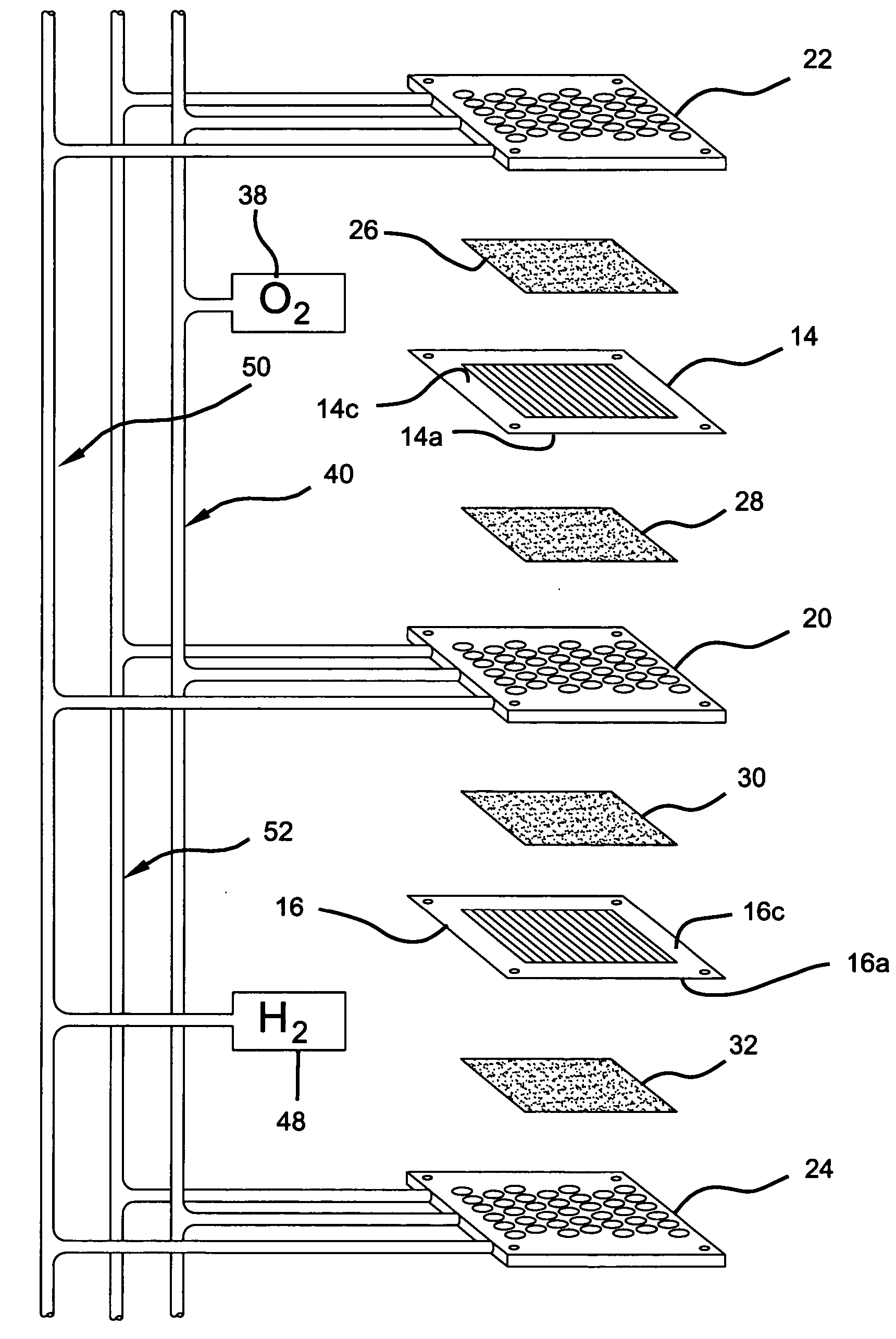
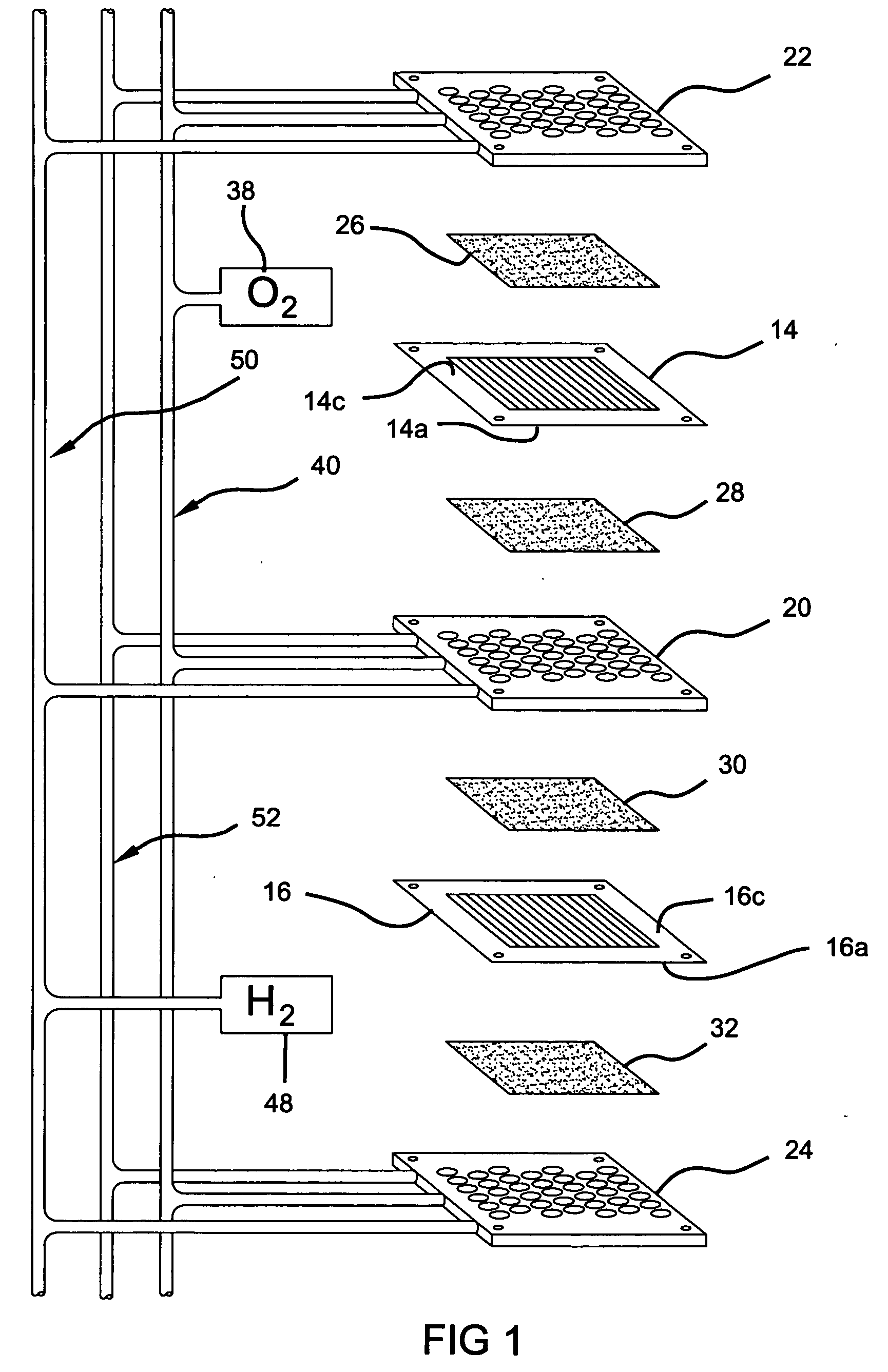
[0032]FIG. 1 schematically depicts a partial PEM fuel cell stack 10 having membrane-electrode-assemblies (MEAs) 14, 16 separated from each other by a non-porous, electrically-conductive bipolar plate 20. The MEAs 14 and 16 and bipolar plate 20 are stacked together between non-porous, electrically-conductive, bipolar plates 22 and 24. Flow-interfering media 26, 28, 30 and 32 which are porous, gas-permeable, and electrically conductive sheets press up against the electrode faces of the MEAs 14 and 16 and serve as primary current collectors for the electrodes. The flow-interfering media 26, 28, 30 and 32 also provide mechanical supports for the MEAs 14 and 16, especially at locations where the MEAs are otherwise unsupported in the flow field. The flow-interfering media 26, 28, 30 and 32 further provide a fluid transport m...


PUM

PropertyMeasurementUnit
Pressureaaaaaaaaaa
Electrical conductivityaaaaaaaaaa
Flow rateaaaaaaaaaa

Abstract

The present invention is directed to a planar flow field design having an intake manifold and an exhaust manifold which are configured in two offset planes. A relatively short passage extends from the intake manifold through the exhaust manifold and terminates at a reactive face of a membrane electrode assembly (MEA) such that a differential flow distribution is provided from the intake manifold through the passage and across a reactive face of the MEA to the exhaust manifold.

Description

FIELD OF THE INVENTION [0001] The present invention relates to PEM fuel cells and more particularly to a separator flow field plate in which relatively small pressure drop is required to achieve the necessary flow rates. BACKGROUND OF THE INVENTION [0002] Fuel cells have been used as a power source in many applications. For example, fuel cells have been proposed for use in electrical vehicular power plants to replace internal combustion engines. In proton exchange membrane (PEM) type fuel cells, hydrogen is supplied as the fuel to the anode of the fuel cell and oxygen is supplied as the oxidant to the cathode. PEM fuel cells include a membrane electrode assembly (MEA) comprising a thin, proton transmissive, non-electrically conductive, solid polymer electrolyte membrane having the anode catalyst on one face and the cathode catalyst on the opposite face. The MEA is sandwiched between a pair of non-porous, electrically conductive elements or plates which (1) serve as current collector...

Claims


Application Information

Patent Timeline
IPC IPC(8): H01M8/02H01M8/10H01M8/24
CPCH01M8/0206H01M8/0221H01M8/0228Y02E60/50H01M8/0258H01M8/1002H01M8/241H01M8/0256H01M8/1007H01M8/2457H01M8/2483H01M8/0273
Inventor MURPHY, MICHAEL W.GU, WENBINDIPIETRO, LEWIS J.
Owner GM GLOBAL TECH OPERATIONS LLC
Learn More