
Flat-flamed burner

A plane flame and burner technology, applied in burners, gas fuel burners, combustion methods, etc., can solve the problems of low safety and reliability, inconvenient improvement and maintenance, system errors, etc., and achieve improved safety and stability, good gas The effect of tightness and reducing the interference of flames

Inactive Publication Date: 2012-06-20
NAT UNIV OF DEFENSE TECH
View PDF4 Cites 13 Cited by
  • Summary
  • Abstract
  • Description
  • Claims
  • Application Information

AI Technical Summary

Problems solved by technology

[0006] The purpose of the present invention is to overcome the deficiencies of the prior art, mainly to solve the problems of systematic error, inconvenient operation, low safety and reliability, and inconvenient maintenance for later improvement when the optical measurement technology is applied to the existing device, and to provide a compact structure and easy operation. , high safety and reliability, improved maintenance convenience, can reduce optical measurement error, and generate a more stable modular planar flame burner

Method used


Image

  • Flat-flamed burner
  • Flat-flamed burner
  • Flat-flamed burner

Examples


Embodiment 1

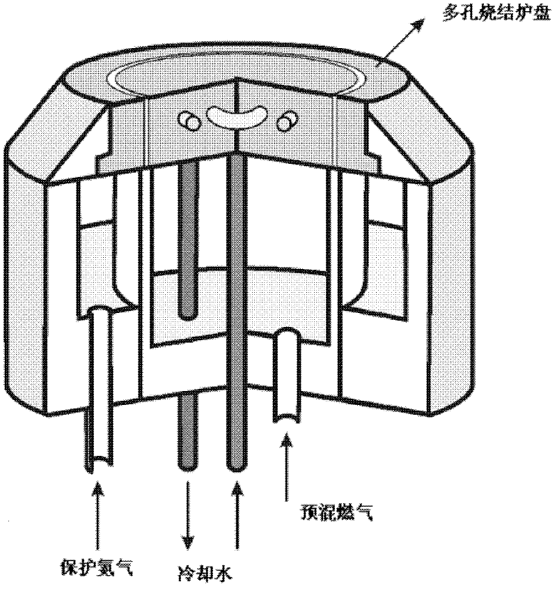
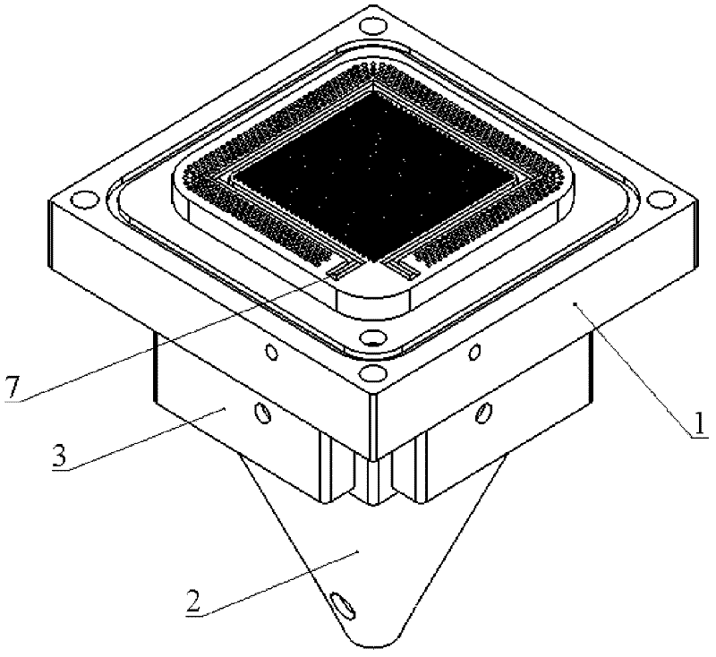
[0104] A flat flame burner, which is composed of a furnace pan 1, a premixed gas chamber 2, and a protective gas chamber 3. The furnace pan 1, the premixed gas chamber 2, and the protective gas chamber 3 are connected coaxially, and the center of the protective gas chamber 3 is inserted The premixed gas chamber 2 is matched with the connection;

[0105] The furnace plate 1 is composed of a base 17 and a test bench 18: the shape of the base 17 is a square when viewed from above, the four top corners are opened with connecting through holes 12, the upper surface is designed with a sealing groove 16, and a cooling liquid hole 24 is designed on each of the two sides A spark plug assembly hole 26 is designed between the seal groove 16 in the top corner area and the test bench 18, the seal groove 16 is located on the periphery of the test bench 18, the groove size is determined according to the mechanical design manual, and one end of the coolant hole 24 is opened on the side of the ...

Embodiment 2

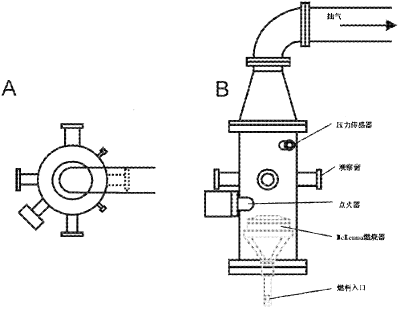
[0109] A flat flame burner, composed of a furnace tray 1, a premixed gas chamber 2, a protective gas chamber 3, an experimental cabin 4, an exhaust cover 5, a pressure regulator 6, an observation window glass 9, and a glass sealing cover 10; 1 is coaxially docked with the premixed air chamber 2, the protective air chamber 3, and the experimental cabin 4, the center of the protective air chamber 3 is inserted into the premixed air chamber 2 and connected, and the experimental cabin 4 is coaxially docked with the exhaust cover 5. The exhaust cover 5 is connected with the pressure regulator 6 through the pipeline, the observation window glass 9 is put into the glass window 38 of the experimental cabin 4, and the glass sealing cover 10 is fixed and sealed;

[0110] Wherein the structure of the stove plate 1, the premixed gas chamber 2, and the protective gas chamber 3 is the same as that of Embodiment 1, only the following parameters are different: the gas nozzle 21 tube diameter i...


PUM


Abstract

The invention discloses a flat-flamed burner. The flat-flamed burner comprises such modules as a stove plate (1), a pre-mixing air chamber (2), a protective air chamber (3), an experimental chamber (4), an air exhaust cap (5), a pressure regulator (6), observation window glass (9), a glass sealing cover (10), and the like. The flat-flamed burner is a modularization flat-flamed burner which is compact in structure, convenient in operation, high in safety and reliability, convenient to maintain after the improvement, capable of reducing photometric errors, self-adjustable in pressure and more stable in the generated flat flame. Different modules are designed, and then assembled to a burner of different functions, so that the modularization design method can constantly expand the application range of the flat-flamed burner.

Description

technical field [0001] The invention relates to a burner, in particular to a self-adjustable pressure modularized plane flame burner suitable for the technical field of optical combustion diagnosis. Background technique [0002] Combustion diagnosis using optical measurement technology is the main method to study the combustion mechanism at present, and the combustion diagnosis experimental system is an important factor affecting the experimental process and results. The planar flame burner is used to generate a planar flame. As an instrument and equipment for combustion diagnosis experiments, its design and manufacturing level will directly affect the efficiency of scientific research and the accuracy of experiments. [0003] The most widely used flat flame burner is the McKenna flame furnace, which is used in the document "Laser Diagnostics Of Trace Species In Low-Pressure Flat Flame" ("Progress in Energy and Combustion Science" Vol.352009 Page: 365-382) McKenan flame fur...

Claims


Application Information

Patent Timeline
Patent Type & Authority Applications(China)
IPC IPC(8): F23D14/02F23D14/26F23D14/46F23D14/64F23D14/76F23D14/78F23D14/82
Inventor 谭建国龙潭王振国周进刘卫东梁剑寒王宁曾科
Owner NAT UNIV OF DEFENSE TECH
Learn More