
Induction magnetometer

Inactive Publication Date: 2005-07-21
UNIVERSITY OF NEW BRUNSWICK
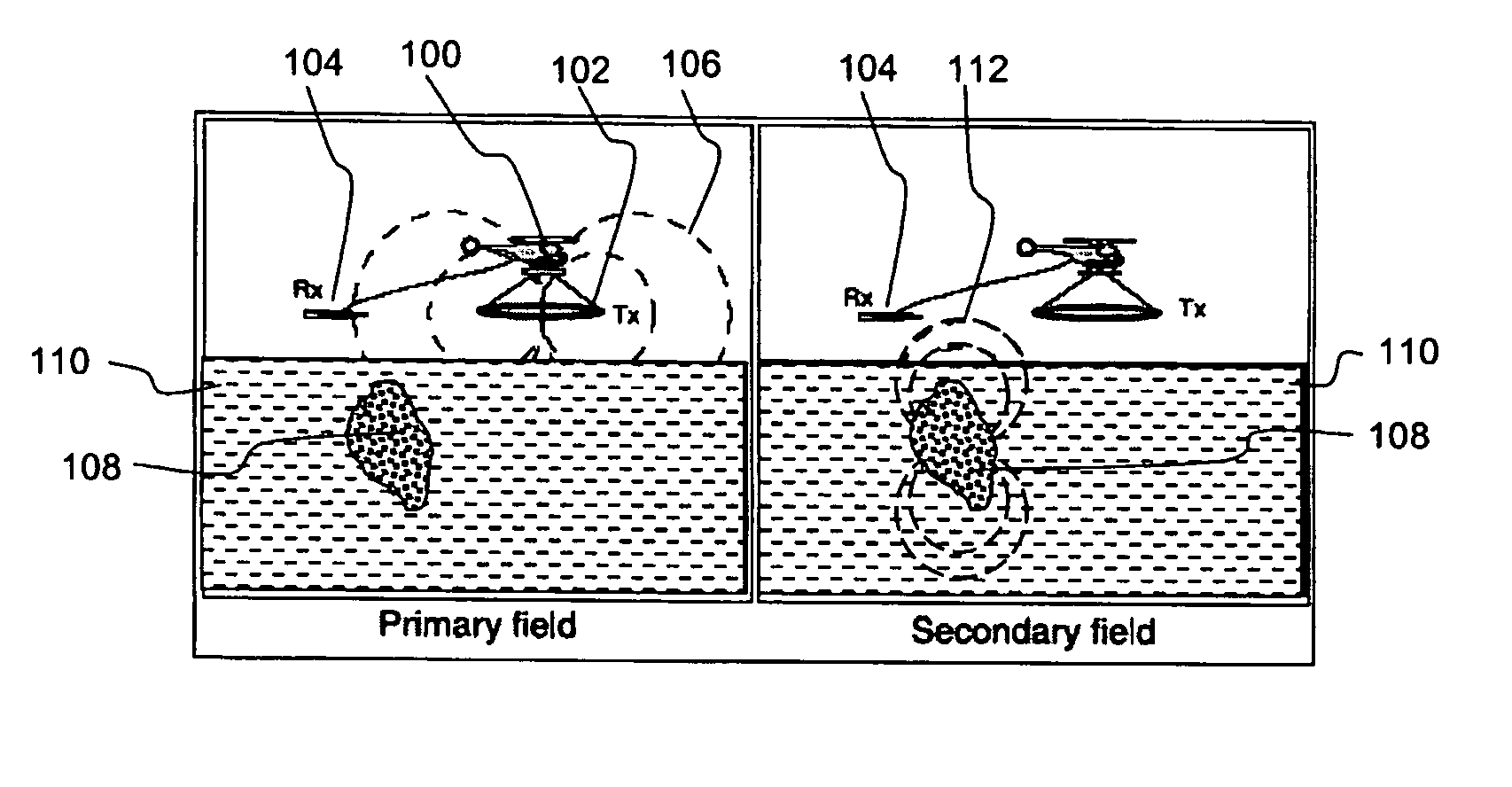
View PDF16 Cites 29 Cited by
  • Summary
  • Abstract
  • Description
  • Claims
  • Application Information

AI Technical Summary

Benefits of technology

[0018] It is therefore an advantage of the present invention to provide an improved induction magnetometer for use in airborne geophysical exploration.
[0019] Another advantage of the present invention is to provide an improved arrangement for calibration of an induction magnetometer for airborne geophysical surveys.
[0020] Briefly, the present invention provides an improvement over known induction magnetometers by using several smaller diameter cores instead of a single larger diameter core. Each smaller diameter core has an increased length-to-diameter ratio which increases the apparent permeability of the cores. The reduction in core cross-sectional area is compensated for by having multiple cores. Spreading the coil windings over several cores, instead of just one, allows for smaller circumference windings over the small diameter cores resulting in less total wire length being required which reduces noise and weight. Multiple smaller coils with fewer windings each also reduces inductance and allows for increased bandwidth.
[0021] The configuration of the individual elemental induction magnetometers in a cube arrangement allows for a very compact package, whose symmetry and hollow aspect permits the incorporation of a calibration field source in the center of the package, thus taking up no additional space and allowing for a permanent calibration system which is easy to use and can be used in flight.
[0022] An embodiment of the present invention provides an induction magnetometer array for airborne geophysical exploration. The magnetometer array comprises a plurality of elemental induction magnetometers. Each elemental induction magnetometer comprises a permeable core and a multi-turn coil surrounding at least a portion of the core. The cores of the elemental induction magnetometers are arranged such that their longitudinal axes are mutually parallel and the output signals from each elemental induction magnetometer are aggregated.
[0023] Another embodiment of the present invention provides an orthogonal induction magnetometer for airborne geophysical exploration. The orthogonal induction magnetometer comprises a plurality of magnetometer arrays. Each magnetometer array comprises a plurality of elemental induction magnetometers. Each elemental induction magnetometer comprises a permeable core and a multi-turn coil surrounding at least a portion of the core. The cores of each array are arranged such that their longitudinal axes are mutually parallel and the output signals from the elemental induction magnetometers are aggregated. The magnetometer arrays are arranged in a mutually orthogonal fashion and the longitudinal axes of the cores correspond to edges of a rectangular parallelepiped.

Problems solved by technology

Helicopter systems have restraints such as high flight-time costs.
To control such costs, it is advantageous to use smaller helicopters, but smaller helicopters have limited payload capacity.
Without the flux concentrating effects of a permeable core, these conventional induction magnetometers tend to be awkward to work with because of their size and weight.
The type of sensors used in most of these applications are not of the inductive type and are not suited for use in ATEM.
One source of noise in such an ATEM system is from vibration caused by the motion of the sensors relative to the Earth's magnetic field and the secondary field.
This resonance limits the usable bandwidth.
Although the spacing introduced decreases the capacitance, it increases the length of wire required to make the same number of turns and thus increases the weight and the resistance of the winding.
Increasing the number of windings in the coil also increases the weight of the coil, which is not desirable for magnetometers used for ATEM.
Larger diameter cores will also capture more flux, but such cores will also be heavier, which is not desirable for magnetometers used for ATEM.
Finite length permeable rod cores have non-uniform flux along their length.
Also, an induction magnetometer having a longer permeable core will have a higher inductance, and unfortunately, also higher weight and longer length, neither of which are desirable for magnetometers used for ATEM.
This is labor intensive, and time consuming, thus it is generally only done once before every survey.
If the system malfunctions during the survey, the reliability of the data is compromised and the survey will have to be re-flown, adding considerable cost.

Method used


Image

  • Induction magnetometer
  • Induction magnetometer
  • Induction magnetometer

Examples


Embodiment Construction

[0042] Improvements to the design of existing orthogonal induction magnetometers are constrained by certain factors. The ability of the core to concentrate the flux is determined by its apparent permeability. The overall amount of flux which passes through the winding is partially determined by the cross-sectional area of the core. The apparent permeability of the core is strongly influenced by its geometry. The longer the core, the higher the length-to diameter ratio and thus the higher the apparent permeability. In ATEM, the length of the induction magnetometers used is limited by the size of the pod in which it is to be mounted. The pod dimensions are constrained by the payload and aerodynamic drag capacity of the towing helicopter. The core diameter determines the cross-sectional area of the core and the apparent permeability of the core. A decrease in core diameter will increase the apparent permeability of the core but will decease the area of the core. These parameters alone ...


PUM


Abstract

An array of induction magnetometers for use in airborne transient electromagnetic (ATEM) geophysical exploration is disclosed, having similar weight and external dimensions of prior art induction magnetometers but with improved signal strength, signal-to-noise ratio, higher frequency, self-resonance and bandwidth, and providing accurate and well monitored calibration.

Description

CROSS-REFERENCE TO RELATED APPLICATIONS [0001] This application claims priority from Canadian patent application 2,450,837, filed Nov. 25, 2003. MICROFICHE APPENDIX [0002] Not Applicable. TECHNICAL FIELD [0003] The present invention relates to magnetometers and more particularly to induction magnetometers for airborne transient electromagnetic geophysical exploration. BACKGROUND OF THE INVENTION [0004] Airborne Transient ElectroMagnetic (ATEM) methods for geophysical exploration are well known in the art. Such methods are appropriate for finding ore bodies in the ground, especially if large areas are to be explored in remote regions which are not easily accessible from the ground. Certain types of ore bodies are highly conductive compared with their surroundings and are therefore well suited to detection by electromagnetic systems. [0005] New helicopter ATEM systems provide a lower noise platform which can be flown more slowly and at lower altitude than fixed wing aircraft systems a...

Claims


Application Information

Patent Timeline
IPC IPC(8): G01R33/028G01V3/10
CPCG01V3/10G01R33/028
Inventor DUPUIS, JEROME CHRISTIANCOLPITTS, BRUCE GORDONPETERSON, BRENT ROBERT
Owner UNIVERSITY OF NEW BRUNSWICK
Learn More