Method and apparatus for the prevention of critical process variable excursions in one or more turbomachines

Active Publication Date: 2005-07-14
COMPRESSOR CONTROLS LLC
View PDF7 Cites 16 Cited by
  • Summary
  • Abstract
  • Description
  • Claims
  • Application Information

AI Technical Summary

Benefits of technology

[0014] A purpose of this invention is to provide a method and apparatus for limiting or constraining critical variables, herein referred to, generically, as “L,” associated with a turbocompressor. Another purpose is to initiate limit-control action such that a limited variable does not cross its base set point. Still another purpose of the present invention is to carry out limit control and the transfer between primary variable control and limit control smoothly and stably.
[0015] Using a combination of closed loop and open loop responses, the limit-control action is designed to minimize the excursion of critical variables, L, related to a turbocompressor, turbine, expander or its associated process, beyond their set points.
[0017] Fixing the set point for constraint control action can increase the overall response time of the control system. To circumvent this problem, the set point of the constraint-control loop is dynamically adjusted as a function of measurable process disturbances. Care must be taken to ensure that dynamic adjustment to the set point does not result in premature control actions on the manipulated variable (herein generically referred to as “M”) that negatively influence the process. In a preferred embodiment, dynamic correction to the set point of each critical limit variable, L, is made as a function of the first derivative with respect to time, dL / dt, of that critical limit variable. In addition, these set point adjustments are rate limited and bound within acceptable levels in each direction (that is, increasing or decreasing) with the ability to configure independent rates and bounds as required.
[0018] An additional aspect of the present invention involves a fast acting, open loop, control response in the event the closed loop constraint control proves inadequate. An acceptable threshold of overshoot of a critical process variable measured from its defined constraint control set point is used as an indication of the effectiveness of closed loop action. Once the constrained variable has reached this overshoot threshold, a rapid change in the manipulated variable, M, is initiated to bring the constrained variable back to an acceptable value. This rapid alteration of the manipulated variable, M, is known as an “open loop” response. Specific methods of open-loop control action include a configurable step response, or fast ramp output to the manipulated variable. The open-loop output is adjusted for system dead time or hysteresis. The open loop control response may be repeated with appropriate pause between repetitions as needed to bring the operating point out of an undesirable state.

Problems solved by technology

In addition, these set point adjustments are rate limited and bound within acceptable levels in each direction (that is, increasing or decreasing) with the ability to configure independent rates and bounds as required.

Method used


Image

  • Method and apparatus for the prevention of critical process variable excursions in one or more turbomachines
  • Method and apparatus for the prevention of critical process variable excursions in one or more turbomachines
  • Method and apparatus for the prevention of critical process variable excursions in one or more turbomachines

Examples


Embodiment Construction

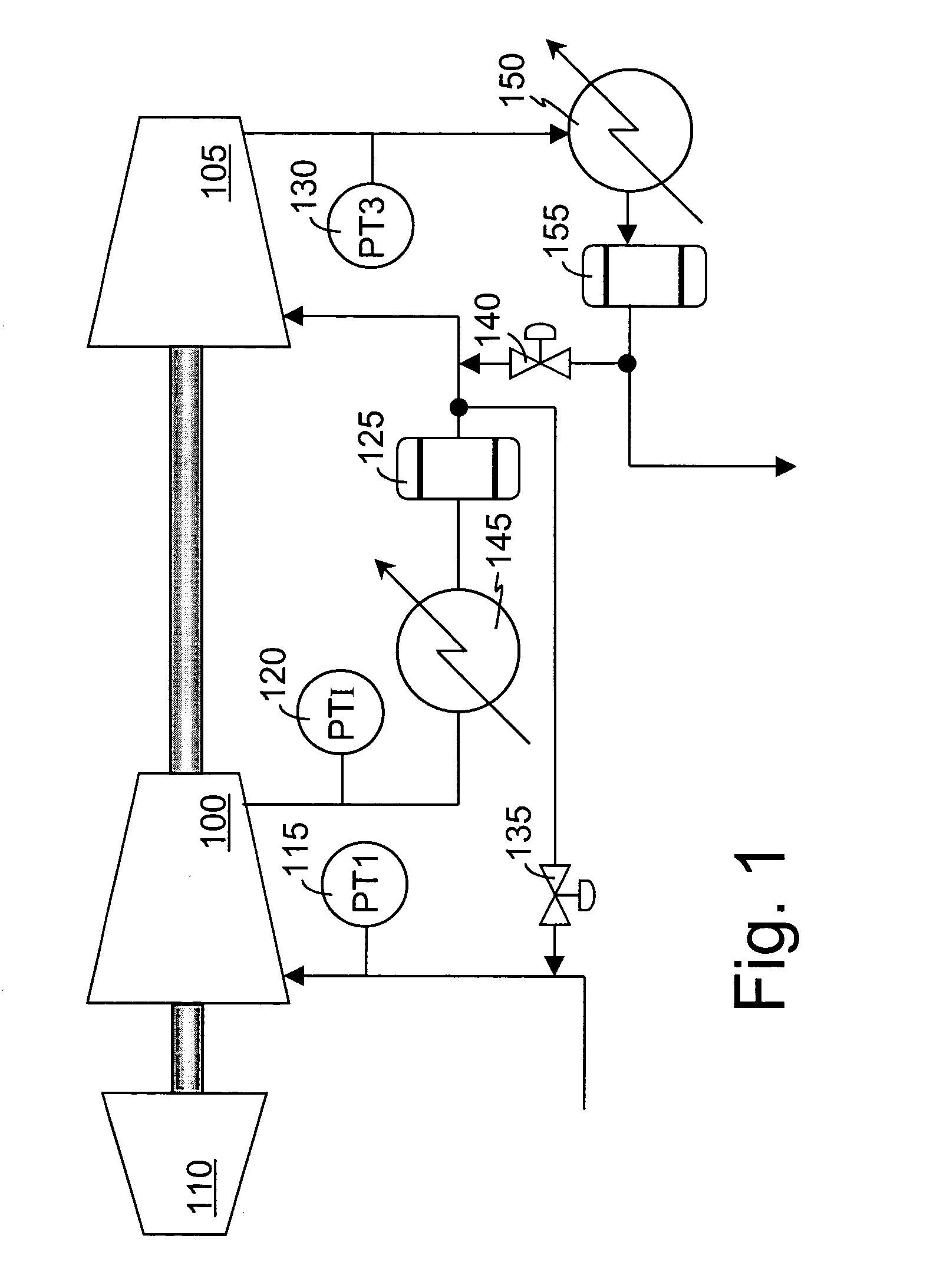
[0040] A typical two-stage compression system is shown in FIG. 1. The two turbocompressors 100, 105, on a single shaft, are driven by a single gas or steam turbine 110. A suction pressure transmitter, PT1115, is provided in the suction of the first compression stage 100. An interstage pressure transmitter, PTI 120, is used to measure a pressure between the compression stages 100, 105, preferably located to measure the highest pressure found in the interstage, or the pressure in an interstage vessel 125 having a maximum pressure constraint. The discharge pressure is measured by a discharge pressure transmitter, PT3130. Any of these pressures may require limit control to keep them within predetermined bounds.

[0041] Antisurge valves 135, 140 may be used as manipulated variables, M, for limit control of several limited variables. The low pressure stage's 100 antisurge valve 135 can be used to keep the turbocompressor's 100 operating point in a stable operating region, that is, out of t...


PUM


Abstract

Many variables in processes such as those using turbocompressors and turbines must be limited or constrained. Limit control loops are provided for the purpose of limiting these variables. By using a combination of closed loop and open loop limit control schemes, excursions into unfavorable operation can be more effectively avoided. Transition between open loop and closed loop may be enhanced by testing the direction and magnitude of the rate at which the limit variable is changing. If the rate of change indicates recovery is imminent, control is passed back to the closed loop limit control function.

Description

CROSS REFERENCE TO RELATED APPLICATIONS [0001] Not applicable. STATEMENT REGARDING FEDERALLY SPONSORED RESEARCH OR DEVELOPMENT [0002] Not applicable. REFERENCE TO MICROFICHE APPENDIX [0003] Not applicable. BACKGROUND OF THE INVENTION [0004] 1. Field of the Invention [0005] The present invention relates generally to a control scheme. More particularly the present invention relates to a method and apparatus for more accurately and stably limiting critical variables associated with a process such as those including turbomachines such as a turbocompressor, steam turbine, gas turbine, or expander. [0006] 2. Background Art [0007] The safe operating regime of a turbocompressor is constrained by the machinery and process limitations. A turbine-driven turbocompressor is generally bound by upper and lower limits of a turbine operating speed, a surge line, a choke limit, high discharge or low suction pressure bounds, and / or a power rating of the turbine. Limit control is used to keep the turbo...

Claims


Application Information

Patent Timeline
IPC IPC(8): F04D27/02
CPCF04D27/0284F04D27/0207
Inventor NARAYANAN, KRISHNANFISHER, PAUL F.
Owner COMPRESSOR CONTROLS LLC
Why Eureka
Try Eureka