Transfer line for transporting workpieces

Inactive Publication Date: 2005-12-15
CROSS HULLER
View PDF8 Cites 0 Cited by
  • Summary
  • Abstract
  • Description
  • Claims
  • Application Information

AI Technical Summary

Benefits of technology

[0006] It is an object of the invention to embody a transfer line of the generic type which is of constructionally simple and thus solid design, allowing inspections of the workpieces between the phases of operation.
[0007] According to the invention, this object is attained in a transfer line with a transporting arrangement, comprising a respective working place at each workstation, the working places having a distance a from each other; a frame to be disposed in front of, and centrally between, the workstations, the frame comprising a depositing place for at least one workpiece; and a transporting beam, which comprises two end areas with a first work support and, at a center distance b therefrom, a second work support, with a ≦2b applying, and which is mounted on the frame for height adjustment between a first position of lifting and a second position of lifting such that the work supports are located above or below the depositing place, and which is longitudinally displaceable between a first position of transfer and a second position of transfer for the first or the second work support to coincide horizontally with the depositing place. The measures according to the invention help create a simple, compact and thus low-cost transfer line. The transporting beam picks up the workpiece in front of a workstation, transfers it to a depositing place where it deposits the workpiece, resumes its original position, is being lifted and then transfers the workpiece to the next workstation. The motion of transfer is divided into two steps, because the workpiece is deposited halfway on the depositing place. This is where it can be inspected either visually or by automatic inspection devices.

Problems solved by technology

This design has the drawback of being comparatively complicated constructionally, there being no possibility of inspection of the phases of operation performed on the first workstation.

Method used


Image

  • Transfer line for transporting workpieces
  • Transfer line for transporting workpieces
  • Transfer line for transporting workpieces

Examples


Embodiment Construction

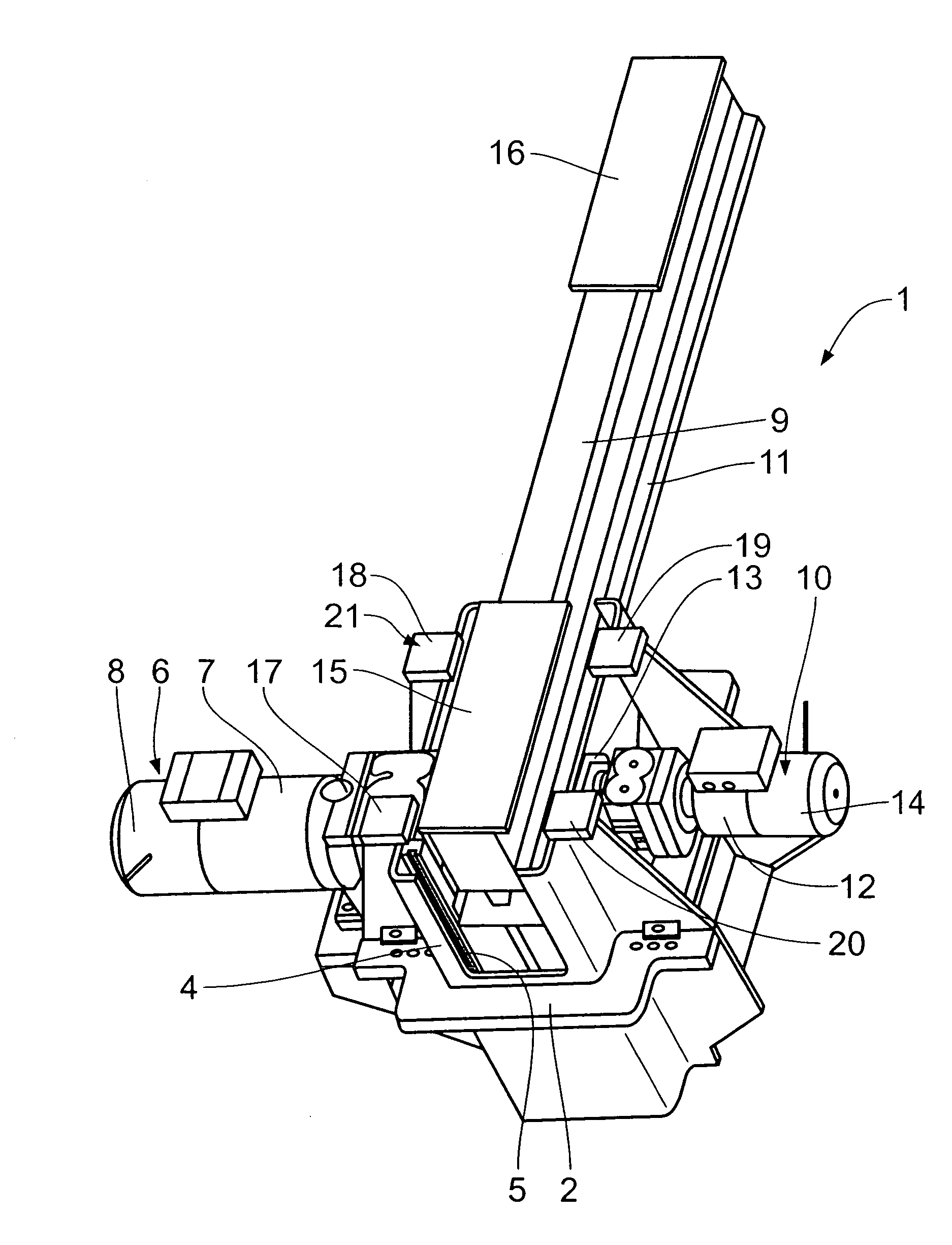
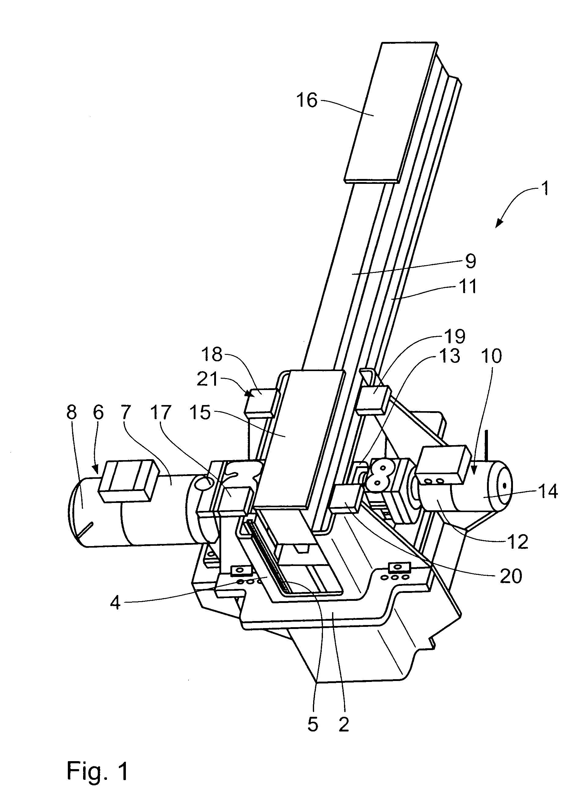
[0012] The transporting arrangement 1 seen in the drawing comprises a frame 2. On the frame 2, a vertically displaceable lifting skid 5 is guided by a vertical guide 4. By means of a lifting drive 6, the lifting skid 5 is vertically movable in the vertical guide 4. The lifting drive 6 is comprised of a servomotor 7 with a conventional position transmitter 8 which transmits the absolute position of height of the lifting skid 5 as a signal to a control system (not shown).

[0013] A transporting beam 9 is mounted in the lifting skid 5 for displacement in the horizontal direction. The transporting beam 9 is horizontally displaceable by means of a transporting drive 10. The drive 10 comprises a rack 11 which is mounted on the transporting beam 9 in the longitudinal direction thereof and which a pinion 13 engages with that is drivable by a servomotor 12. The servomotor 12 is also provided with a position transmitter 14 which detects the absolute position of the transporting beam 9 and tran...


PUM

PropertyMeasurementUnit
Displacementaaaaaaaaaa

Abstract

A transfer line for transporting workpieces from a first workstation to an adjacent second workstation comprises a frame with a depositing place for at least one workpiece. It further comprises a transporting beam, each end area of which having respective work supports. The transporting beam is supported for height adjustment between two positions of lifting such that the work supports are located above or below the depositing place. The transporting beam is further designed for longitudinal displacement between positions of transfer for the work supports to coincide horizontally with the depositing place.

Description

BACKGROUND OF THE INVENTION [0001] 1. Field of the Invention [0002] The invention relates to a transfer line for transporting workpieces from a first workstation to an adjacent second workstation. [0003] 2. Background Art [0004] As a rule transfer lines comprise a plurality of individual workstations which serve for working the same or different types of workpieces. The respective workstation is designed for a given treatment of a workpiece. [0005] WO 03 / 086699 A1 teaches a transporting arrangement of the generic type which comprises a frame that is to be disposed in front of, and centrally between, two adjacent workstations. A transporting beam is longitudinally displaceably supported on the frame, with a workpiece holding skid being disposed on the transporting beam for displacement over the length thereof. For transfer of a workpiece from one workstation to an adjacent workstation, the transporting beam, by its end that adjoins the first workstation, is moved in front thereof and...

Claims


Application Information

Patent Timeline
IPC IPC(8): B23Q7/00B23Q7/14B65G25/02
CPCB23Q7/1484
Inventor CASPER, JURGENSTROHHACKER, KLAUSSCHLEGEL, THOMAS
Owner CROSS HULLER
Why Eureka
Try Eureka