Printed circuit board plug-in connection

a technology for plugging in and printing circuit boards, applied in the direction of coupling contact members, coupling device connections, printed circuit aspects, etc., can solve the problems of only partially automated production, relatively complicated process, and correspondingly high production costs, and achieve the effect of significantly reducing the number of transfer contacts of the plugging in connection

Active Publication Date: 2021-07-01
HARTING ELECTRIC GMBH & CO KG
View PDF0 Cites 1 Cited by
  • Summary
  • Abstract
  • Description
  • Claims
  • Application Information

AI Technical Summary

Benefits of technology

[0011]One particular advantage of embodiments of the invention is that the at least one pin contact can be plugged directly into corresponding passage contact openings of the printed circuit board and in this way can be electrically contact-connected to the contact material, which is located in said passage contact openings, of the corresponding conductor track. Finally, the number of transfer contacts of the plug-in connection is considerably reduced in this way.
[0012]Since the printed circuit board connector has at least one slot which starts at the plug-in end and runs through its pin axis in the direction of the cable connection region, it can apply the elasticity required for the plug-in connection. In particular, its segments can move at least slightly toward one another during the plug-in operation with application of a corresponding counterforce.
[0015]It is particularly advantageous for at least two, in particular identical, segments of the printed circuit board connector that are free-standing in the plug-in direction to be formed in the pin contact by said at least one slot in its connecting region and in the plug-in region. These at least two segments each point in the direction of the plug-in end and can be moved at least slightly toward one another by an at least slight elastic deformation of the printed circuit board connector, for example, by pressing together its plug-in region, by way of their free-standing ends. Owing to its at least one slot and its elasticity, in particular its at least slightly reversibly deformable material, in particular metal, the printed circuit board connector finally has the at least slight deformability which is required for this purpose.
[0017]In a particularly advantageous refinement, the printed circuit board connector additionally has a second slot which likewise starts at the plug-in end and runs in the direction of the cable connection region, which second slot intersects the first slot in said pin axis, in particular at a right angle. This is particularly advantageous because the elasticity of the printed circuit board connector is increased in this way. Finally, four, in particular identical, segments of the printed circuit board connector are formed in this way, which segments can be in particular equally, for example, in the direction of the pin axis, at least slightly elastically deflected with application of a corresponding counterforce. The outer surfaces of the segments can advantageously be designed in the form of a segment of a circle and therefore fit in an optimum manner into the, in particular, round passage contact opening.
[0023]In a further advantageous refinement, the slot / slots ends / end either in the connecting section or at the latest at the end of the connecting section. This is particularly advantageous because the cable connection region, which is provided for making contact with the printed circuit board, is of solid design in this way since it therefore has no slots. Finally, said cable connection region can be particularly readily soldered to the first printed circuit board as a result.
[0025]In an advantageous refinement, the printed circuit board connector, in its basic form, can be a rotary part. As a result, it is very stable and can be produced in an automated and therefore cost-effective manner. In particular, the at least one slot can be made in the pin contact with only a low level of expenditure, for example, by sawing or milling.

Problems solved by technology

One disadvantage in this prior art is that, during production, the contact spring is initially produced using a stamping and bending process and usually arranged in the insulating body and has to be held in said insulating body, for example, by latching.
These processes are relatively complicated and can be only partially automated.
Therefore, production is correspondingly expensive.

Method used


Image

  • Printed circuit board plug-in connection
  • Printed circuit board plug-in connection
  • Printed circuit board plug-in connection

Examples


Embodiment Construction

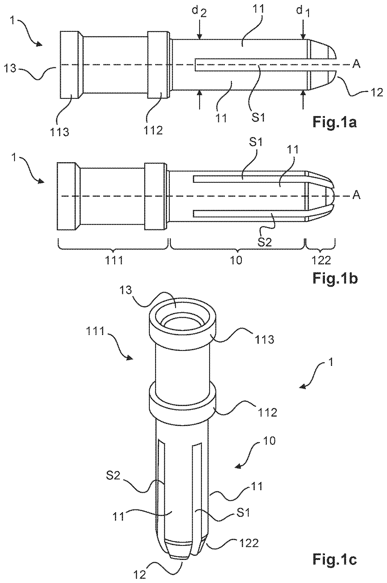
[0041]FIGS. 1a-c show various views of a pin contact 1 with an axis of symmetry which is denoted pin axis A. The pin contact 1 has a cable connection region 111 which is designed as a crimp region. The cable connection region 111 is of hollow-cylindrical form in the basic state, that is to say in the non-crimped state, and has, at its cable connection-side end, a cable insertion opening 13 with an insertion collar 113 for receiving and making electrical contact with a core of an electric cable, not illustrated in the drawing. At its other end, the cable connection region 111 has a connecting collar 112 by way of which it is connected to a connecting section 10.

[0042]At its plug-in end 12, the pin contact 1 has a tapering section 122 which is connected to the cable connection region 111 by way of the connecting section 10.

[0043]As is clear from FIG. 1a, the pin contact 1 has at least one first slot S1, which starts at the plug-in end 12 and runs through the pin axis A in the directio...


PUM


Abstract

A printed circuit board plug-in connection is provided for transmitting the highest possible currents between a printed circuit board and an electrical cable, the printed circuit board plug-in connection being manufactured as simply and economically as possible. For this purpose, a plug-in connection having a slotted pin contact is proposed. Said pin contact is arranged in an insulating body and can be inserted directly into a passage contact opening of a printed circuit board in order to establish electrical contact. The insulating body has detent arms, which releasably engage in detent openings of the printed circuit board in a locking manner at the same time. By means of dovetail connections, several insulating bodies can be fastened to each other, i.e., can be cascaded with each other. A strain relief element can also be fastened to an insulating body by means of the dovetail connection in order to provide strain relief for individual conductors of the cable.

Description

BACKGROUNDTechnical Field[0001]This disclosure relates to a printed circuit board plug-in connection for connecting an electric cable to a printed circuit board.Description of the Related Art[0002]Printed circuit board plug-in connections can have one or more electrical plug-in contacts and are required in order to electrically connect an electric cable to a printed circuit board and also to be able to disconnect this connection again with only a low level of expenditure. In particular, printed circuit board plug-in connection then serve to transmit currents of high current intensity, called “high currents” for short, from one or more electrical conductors of the electric cable to one or more conductor tracks of the printed circuit board. Here and below, the terms “high current intensity” / “high currents” mean, in particular, that a plug-in connection of this kind can transmit a current of, for example, at least 10 amperes, in particular at least 16 amperes, for example, at least 24 ...

Claims


Application Information

Patent Timeline
Patent Type & Authority Applications(United States)
IPC IPC(8): H01R12/75H05K1/11H01R12/70H01R13/514H01R13/58H01R13/05
CPCH01R12/75H05K1/115H01R12/7052H01R13/514H05K2201/09072H01R13/58H01R13/052H05K2201/09063H01R12/7023H01R12/585H01R4/20
Inventor KLIEVER, WILHELM
Owner HARTING ELECTRIC GMBH & CO KG
Why Eureka
Try Eureka