Chain guide element

a technology of guide elements and chains, applied in the direction of guards, cycle equipments, gearing, etc., can solve the problems of reducing so as to improve the rigidity of the rail and facilitate fabrication. , the effect of solid design

Inactive Publication Date: 2017-09-19
SCHAEFFLER TECH AG & CO KG
View PDF21 Cites 2 Cited by
  • Summary
  • Abstract
  • Description
  • Claims
  • Application Information

AI Technical Summary

Benefits of technology

[0010]One exemplary embodiment of the invention relates to a chain guide element having a first rail and a second rail spaced from the first rail, there being in each case on both sides of the rails lateral connecting elements that connect the two rails to each other. Two supporting means are provided in order to support the rails so that they are pivotable and linearly movable. A first supporting means is positioned on the lateral connecting elements, and a second supporting means works together with the first supporting means, both of which are positioned to the side of the rails. This results in the supporting means being positioned at the level of the chain which is running between the rails of the chain guide, and the pivot point being located at the level of the chain so that the pivoting motion of the chain guide is essentially only a rotational motion. It also results in the supporting means being provided to the side of the rails, and thus to the side of the chain, so that more construction space is available for the rails and for the connecting element, and so that the rails and connecting element can be of a more solid design, which has a positive effect on the rigidity of the rails and on the ease of fabrication.
[0012]It is also advantageous if the first supporting means in each case have a receptacle which is engaged in each case by a projection of the first supporting means, or if the first supporting means in each case have a projection which in each case engages a receptacle of the second supporting means. Secure support of the chain guide element by means of the first and second supporting means is achieved thereby. Accordingly, the chain guide element can pivot around the projection by means of the receptacle. If the receptacle is elongated, a radial equalization can also occur.
[0013]It is also advantageous if the projection and the receptacle are positioned essentially at the level of the chain in the chain guide element.
[0014]In addition, it is useful if the second supporting means are connected on an axis which is spaced from the first and second supporting means. This enables the second supporting means to be connected via the axis with a transmission housing. If the axis runs in the zone between the conical disk pairs of the chain-driven, conical-pulley transmission, then construction space can also be saved.

Problems solved by technology

This leads to disadvantages, which are also caused in particular by the fact that a guide tube crossing the construction space or a bolt is used to support the chain guide element.
The use of the construction space by the receptacle located below the rails means that the construction space for the rails and the connecting element is limited, which results in these components having to be of relatively narrow design, which has a negative effect on their rigidity.
This also has negative effects on the damping of strand vibrations of the first and second orders, and on the fabrication.

Method used


Image

  • Chain guide element
  • Chain guide element
  • Chain guide element

Examples


Embodiment Construction

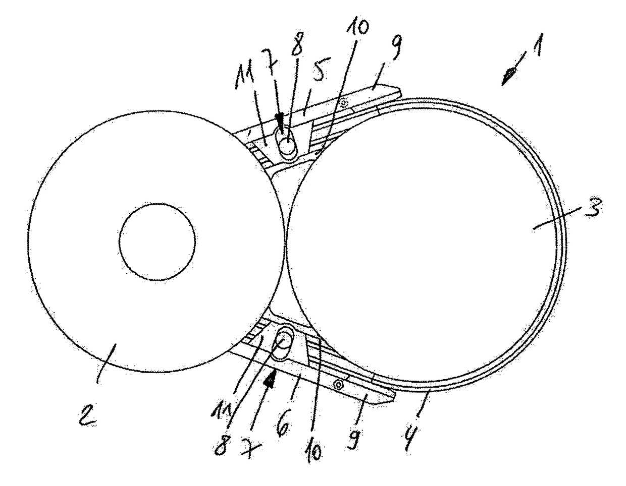
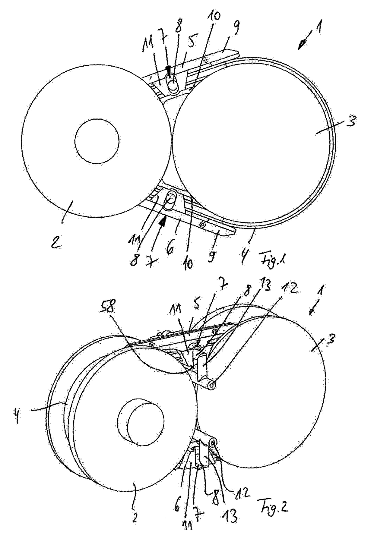
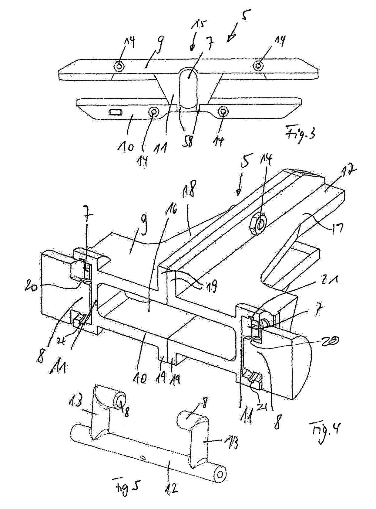
[0030]FIG. 1 shows a chain-driven converter 1, in particular of a continuously variable transmission or CVT transmission, having a first conical disk pair 2 and a second conical disk pair 3. Positioned between the two conical disk pairs 2,3, as an endless torque-transmitting means, is a chain 4 encircling the two conical disk pairs 2,3. To guide the chain 4 between the two conical disk pairs 2,3, a first chain guide element 5 and a second chain guide element 6 are provided, which guide the chain in passing from the first conical disk pair 2 to the second conical disk pair 3 and vice versa. The chain guide elements 5,6 are supported by supporting means 7,8 so that they are pivotable and linearly movable, so that the arrangement of the respective chain guide elements 5,6 is able to adapt to the course of the chain 4.

[0031]The chain guide elements 5,6 include a first rail 9 and a second rail 10, which are spaced from each other to form an intermediate space in which the chain 4 runs wi...


PUM


Abstract

A chain guide element having a first guide rail and a second guide rail which is spaced from the first guide rail to guide a moving chain therebetween. On each lateral side of the chain guide element connecting elements connect the two guide rails in spaced relationship to slidably receive a moving chain. First supporting elements are positioned on the laterally arranged connecting elements that connect the first and second guide rails, and second supporting elements are carried by a stationary component to cooperate with the first supporting elements so that the chain guide element is pivotable and is linearly movable relative to the second supporting elements.

Description

CROSS-REFERENCE TO RELATED APPLICATION[0001]This application is the U.S. national phase application under 35 U.S.C. §371 of International Application Serial No. PCT / DE2014 / 200416, having an international filing date of 21 Aug. 2014, and designating the United States, which claims priority based upon German Patent Application No. DE 10 2013 218 942.7, filed on 20 Sep. 2013, the entire contents of each of which applications are hereby incorporated by reference herein to the same extent as if fully rewritten.BACKGROUND OF THE INVENTION[0002]Field of the Invention[0003]The present invention relates to a chain guide element, in particular for a CVT transmission of a motor vehicle.[0004]Description of the Related Art[0005]Chain guide elements are known in CVT transmissions according to the prior art to guide the chain and damp strand vibrations of the chain.[0006]For example, DE100 17 005 A1 discloses a continuously adjustable, chain-driven conical-pulley transmission as a CVT transmissio...

Claims


Application Information

Patent Timeline
Patent Type & Authority Patents(United States)
IPC IPC(8): F16H7/18F16D1/00F16H57/02F16H9/18F16H9/24B62J13/00
CPCF16H7/18F16H9/18F16H9/24F16H2007/185
Inventor WERNY, PIERREPENNER, STEPHAN
Owner SCHAEFFLER TECH AG & CO KG
Why Eureka
Try Eureka