Eureka AIR delivers breakthrough ideas for toughest innovation challenges, trusted by R&D personnel around the world.

Method for improving well quality

a well quality and well technology, applied in the field of wells, can solve the problems of contaminated oil coming from oil wells, general undesirable contaminants, etc., and achieve the effects of improving the quality of liquid, increasing the amount of cleaner liquid, and increasing the level of radionuclides

Inactive Publication Date: 2005-07-14
AQUASTREAM
View PDF18 Cites 2 Cited by
  • Summary
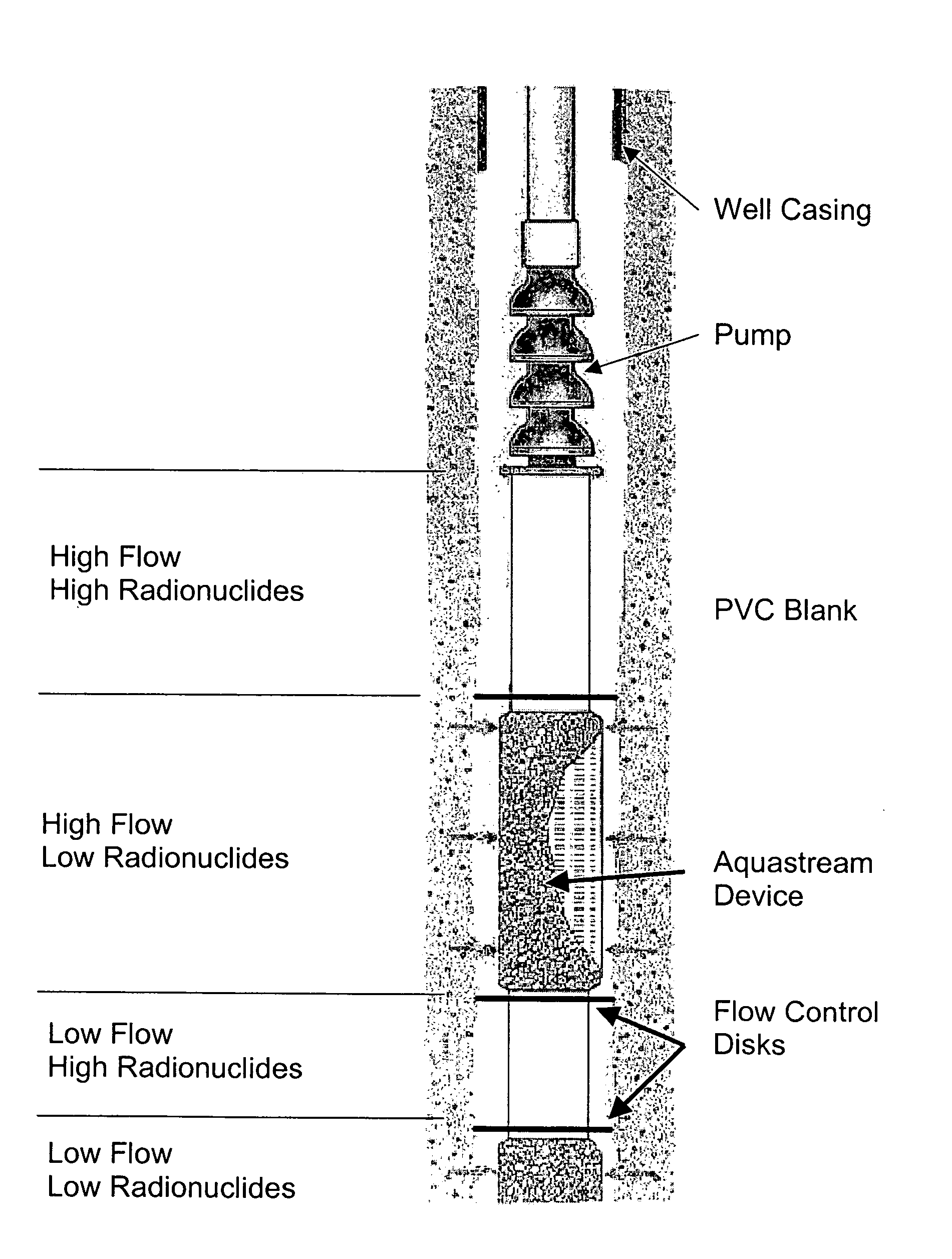
  • Abstract
  • Description
  • Claims
  • Application Information

AI Technical Summary

Benefits of technology

[0006] The present invention provides such a method of improving the quality of liquid drawn from a well. The invention is based on the recognition that liquid within a given well is actually a mixture of liquid from different sections (e.g., depths) within the well, and that the quality of the liquid can vary significantly between sections. For example, water coming from one section of a water well could have significantly higher levels of radionuclides than water coming from a different section of the well. Under normal operation of a well, the liquid pumped from the well is a mixture of liquid from various sections. In accordance with the present invention, the well bore is modified and the well equipment is specifically constructed so that more of the “cleaner” liquid is pumped from the well compared to the more “contaminated” water.
[0007] In order to increase the amount of cleaner liquid coming from the well, the method includes sampling the liquid from the well to determine which sections of the well produce the cleanest liquid. After the various sections of the well have been identified and labeled (e.g., according to their relative amount of contaminants), the well equipment is modified to enhance the amount of liquid being drawn from the cleaner sections of the well and to reduce the amount of liquid drawn from the more contaminated sections of the well. This can be accomplished using a suction flow control device. The suction flow control device includes suction elements that are vertically spaced within the well in order to distribute the suction from the pump along the vertical length of the well. The present invention positions the elements at or near the cleaner sections of the well. More specifically, the present invention utilizes a suction control device so that the suction created by the pump is enhanced in the sections of the well that produce cleaner liquid and is inhibited in the sections of the well that produce more contaminated liquid. By virtue of this design, the contamination level of the liquid being pumped from the well is reduced.
[0008] In order to decrease the amount of liquid flowing from one section of the well to another section of the well (e.g., from a more contaminated section to a less contaminated section), the pump equipment can be provided with flow control disks that extend radially from the suction flow control device (or other part of the pump and pipe assembly) and toward the inner surface of the well. These flow control disks provide a barrier between a more contaminated section and cleaner section, thereby reducing the amount of mixing of liquid from the two sections.
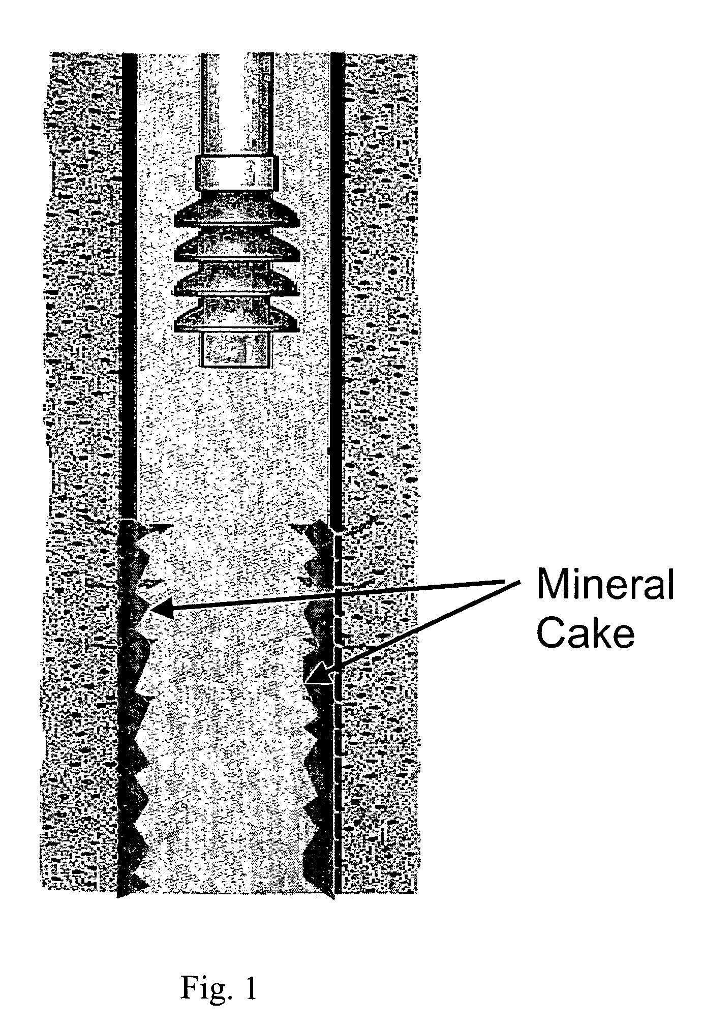
[0009] With specific regard to water wells, the present invention is also based on the theory that a large amount of the radionuclides found in water is caused by the contamination of the mineral cake found within the well. In a preferred embodiment of the invention, the mineral cake is at least partially removed from the wall of the well, resulting in lower contamination of the water and also a high flow rate of water. Then, the well equipment is modified (e.g., using suction control devices and flow control disks) to enhanced flow from the cleaner sections of the well.
[0010] It is also believed that practicing the present invention will reduce the rate at which the mineral cake re-forms on the walls of the bore. More specifically, the strategic use of a suction flow control device as described above will result in a wider distribution of energy throughout the well. This results in slower-moving water, and a corresponding decrease in pressure drop at the walls of the bore. It is theorized that the decreased pressure drop will result in less precipitation of minerals.

Problems solved by technology

Other contaminants that are generally undesirable include arsenic, iron, and others.
Similar to water wells, oil coming from oil wells can be contaminated.

Method used


Image

  • Method for improving well quality
  • Method for improving well quality
  • Method for improving well quality

Examples


Embodiment Construction

[0015]FIGS. 1-4 illustrate one embodiment of the present invention as used in connection with the treatment of a water well for purposes of reducing the level of radionuclides in water pump from the well. Of course, it should be understood that other contaminants could be removed using the same of similar process. The illustrated embodiment utilizes a two-phase process to reduce contamination of water pumped from a water well.

[0016] Phase I includes gathering data regarding historical well performance, sampling and logging the characteristics of water from different sections of the well, and cleaning the well. Data gathering involves collecting and reviewing historic data about the well. This data includes hydraulic, water chemistry, and geologic information. In the event that recent data is not available at different flow rates, this data can be collected prior to removing the pump. The primary purpose of this step in the process is to provide a base line against which future data...


PUM


Abstract

A method of improving the quality of liquid coming from a well that has a pump and pipe assembly. The method includes identifying a region of the well that is low in contamination and a region of the well that is high in contamination, and modifying the pump and pipe assembly so that suction of the assembly is enhanced in the region that is low in contamination and inhibited in the region that is high in contamination. Modifying the pump and pipe assembly can include coupling a suction control device to the pump and pipe assembly, and positioning the suction control device in the region of low contamination. In addition, modifying the assembly can include positioning a flow control disk in a location that is substantially between the region of low concentration and the region of high concentration.

Description

CROSS-REFERENCE TO RELATED APPLICATIONS [0001] This application is a divisional application of U.S. patent application Ser. No. 10 / 239,738, filed Sep. 25, 2002, which is a §371 of PCT / US01 / 10311, filed Mar. 29, 2001, which claims the benefit of 60 / 192,915, filed Mar. 29, 2000. The entire contents of these applications are hereby incorporated by reference herein.FIELD OF THE INVENTION [0002] The present invention generally relates to wells, such as water wells and oil wells, and specifically relates to methods for improving the quality of the liquid (e.g., water or oil) removed from wells. BACKGROUND OF THE INVENTION [0003] In 1976, the United States Environmental Protection Agency (EPA) promulgated interim drinking water standards under the Safe Drinking Water Act (SDWA). In 1991, the EPA proposed revisions to the 1976 requirements, and in 1996 the SDWA was amended. The amended SDWA established a list of contaminants to be regulated under primary standards and secondary standards. T...

Claims


Application Information

Patent Timeline
Patent Type & Authority Applications(United States)
IPC IPC(8): E03B3/15E21B37/00E21B43/14
CPCE03B3/15E21B43/14E21B37/00
Inventor JACKSON, RICHARD C.JUDKINS, MICHAEL E.
Owner AQUASTREAM
Why Eureka
Eureka Blog
Learn More