Intervertebral body fusion cage with keels and implantation method
- Summary
- Abstract
- Description
- Claims
- Application Information
AI Technical Summary
Problems solved by technology
Method used
Image
Examples
embodiment 100
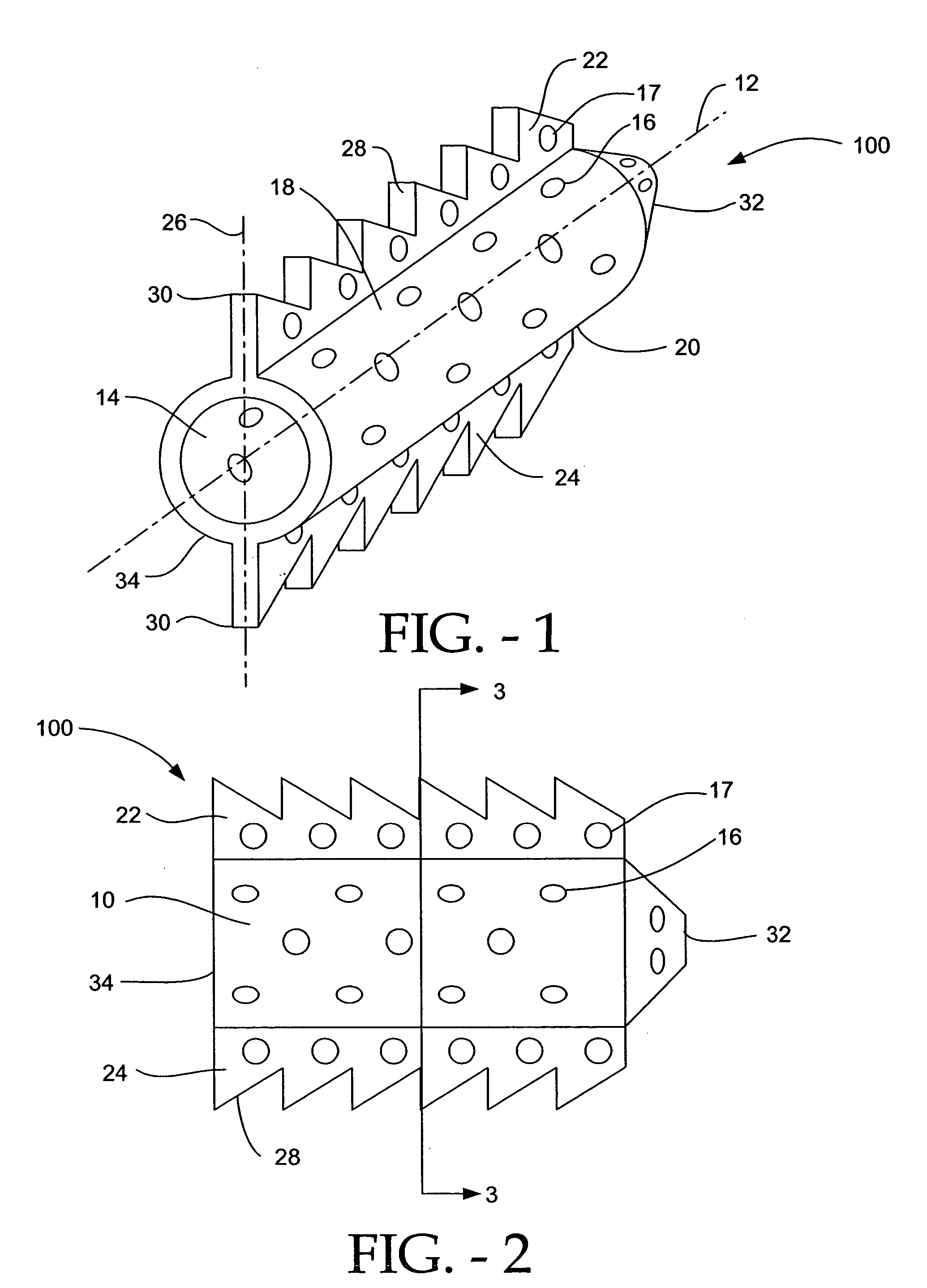
[0044] The cylindrical cage 10 has a superior surface 18 that abuts the upper vertebra of the two affected vertebrae, and an inferior surface 20 that abuts the lower vertebra. In this embodiment 100, a first keel 22, preferably substantially perpendicular to the sagittal plane of the body, extends along the longitudinal axis 12 of the cylindrical cage 10, and into the cancellous bone of the vertebral body of the top vertebra through a keel-receiving channel cut into the vertebral body of the top vertebra. Similarly, a second keel 24, preferably substantially perpendicular to the sagittal plane of the body, extends along the longitudinal axis 12 of the cylindrical cage 10, and into the cancellous bone of the vertebral body of the bottom vertebra through a keel-receiving channel cut into the vertebral body of the bottom vertebra. The keels include apertures 17 that allow the patient's vertebral bone to grow through to further stabilize and integrate the implant 100 into the upper and ...
embodiment 200
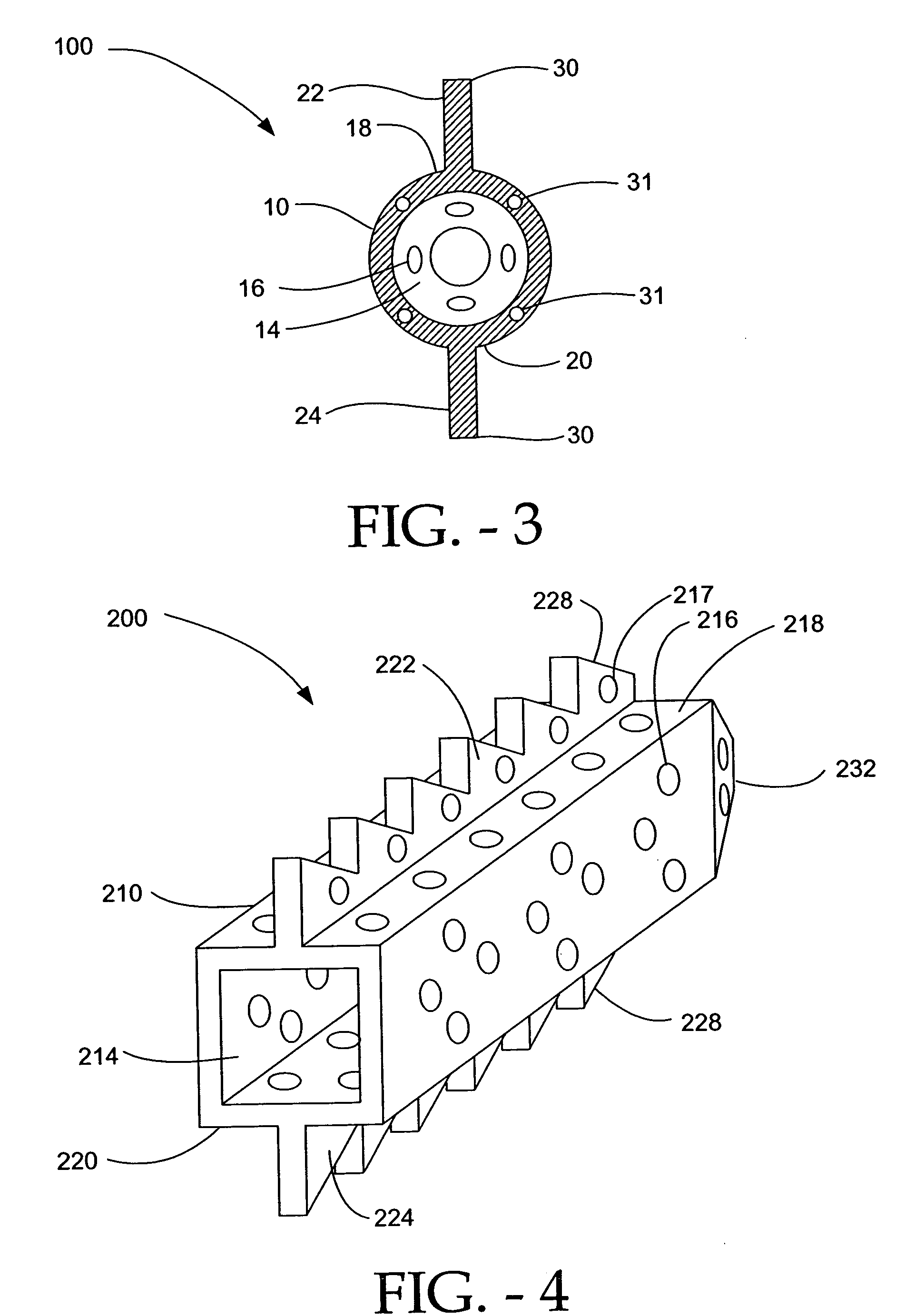
[0056]FIGS. 4-6 depict an embodiment 200 of the disclosed implant having a cage 210 with a cubical configuration. The cubical configuration can enhance the communication of the bone graft and bone growth-promoting contents contained in the hollow interior 214 of the cubical cage 210 by bringing a greater surface area of the cage 210, and hence, a greater amount of bone graft material, into direct contact with the cancellous bone of the vertebral bodies. Further the flat superior 218 and inferior 220 planar surfaces of the cage 210 create stabilizing surfaces that mate with the upper and lower end plates of the upper and lower vertebrae. It is to be understood that, for all embodiments, the vertebrae may be somewhat shaped in order to accept the superior 218 and inferior 220 planar surfaces of the cage 210.
[0057] As with the embodiments previously described, a plurality of keels 222, 224 is contemplated, extending from the superior 218 and inferior 220 surfaces of the cage 210 of the...
embodiment 400
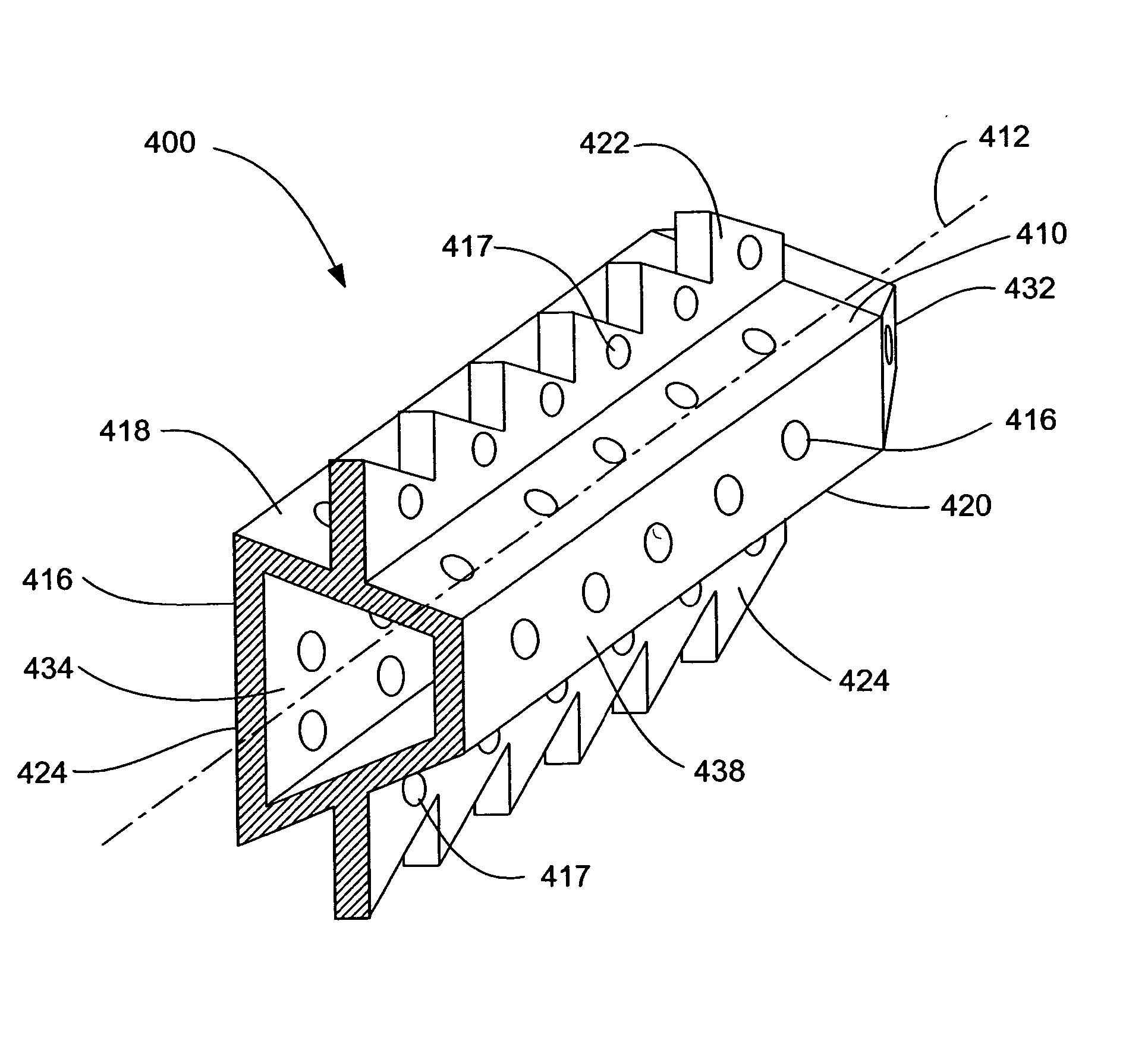
[0064] It should be appreciated that embodiment 400 also can be implanted from an anterior or posterior approach. Either of those approaches would correct lateral curvature of the spine.
[0065]FIGS. 11-13 depict a further embodiment 500 of the disclosed implant. This embodiment 500 is similar to the embodiment 400 in FIGS. 8-10, with the difference being that the narrowest 538 and widest 540 surfaces of embodiment 500 are arranged opposite to their respective positions in embodiment 400. Like embodiment 400, embodiment 500 can be implanted laterally to restore normal curvature to the spine; alternatively, if implanted from an anterior or posterior approach, embodiment 500 would correct lateral curvature of the spine.
[0066] As discussed above, scoliosis, or abnormal lateral curvature of the spine, can also be corrected by positioning a wedge-shaped implant with keels in the intervertebral space. The implant can be constructed for different angles of correction, as with the implant fo...
PUM
 Abstract
Description
Claims
Application Information
 - R&D
- Intellectual Property
- Life Sciences
- Materials
- Tech Scout
- Unparalleled Data Quality
- Higher Quality Content
- 60% Fewer Hallucinations
Browse by: Latest US Patents, China's latest patents, Technical Efficacy Thesaurus, Application Domain, Technology Topic, Popular Technical Reports.
© 2025 PatSnap. All rights reserved.Legal|Privacy policy|Modern Slavery Act Transparency Statement|Sitemap|About US| Contact US: help@patsnap.com


