Data readout arrangement
a data and readout technology, applied in the field of data readout arrangement, can solve the problems of system read performance being slower than desired, slower than desired, and slower than desired
- Summary
- Abstract
- Description
- Claims
- Application Information
AI Technical Summary
Problems solved by technology
Method used
Image

Examples
first embodiment
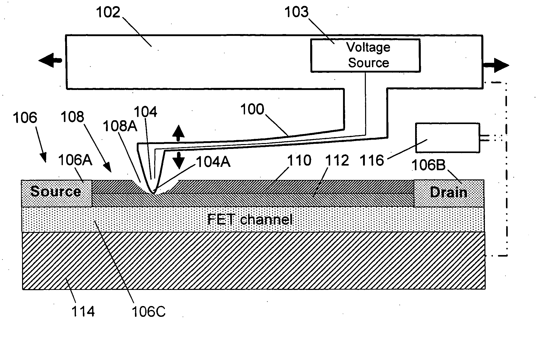
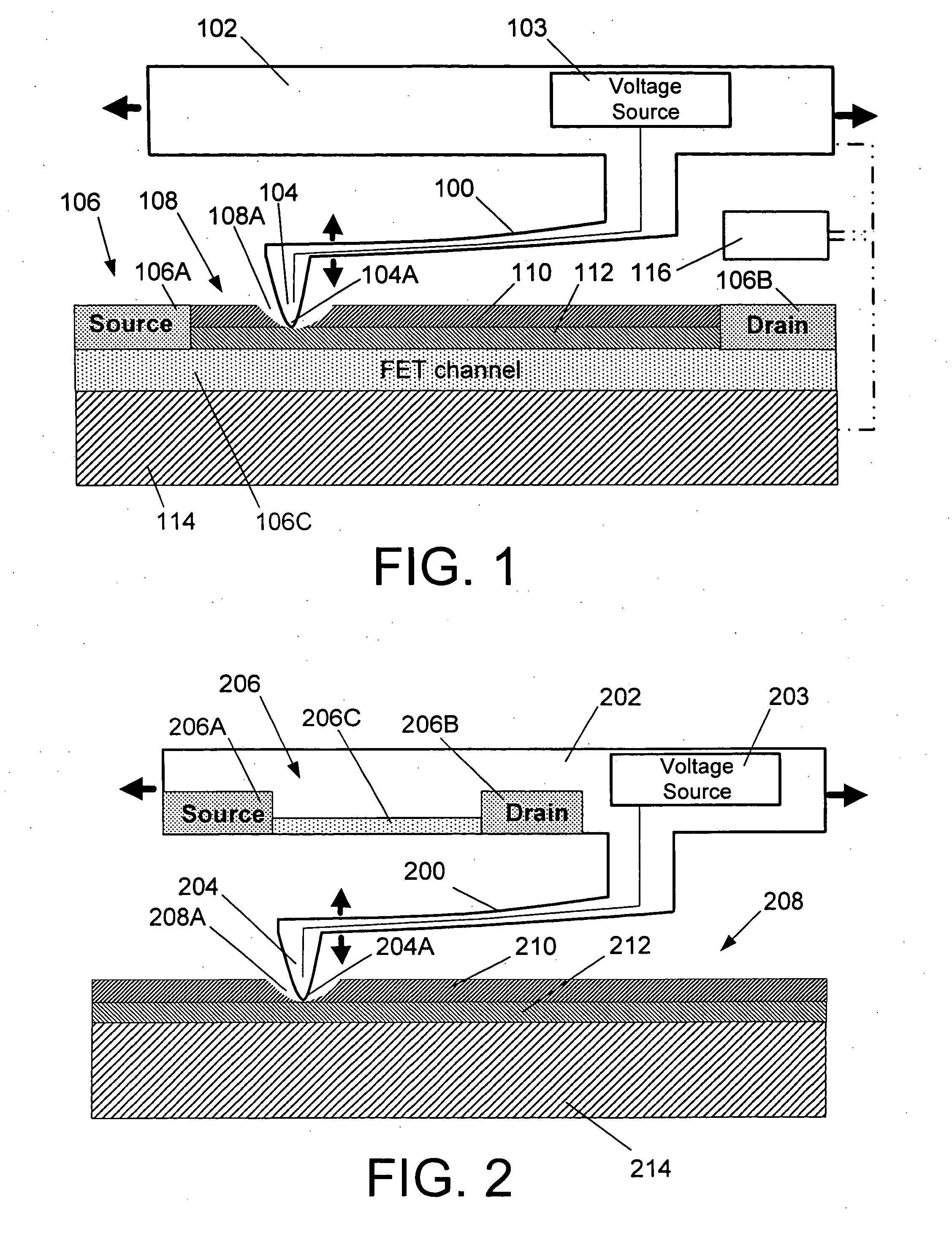
[0013]FIG. 1 shows the invention. In this arrangement, a flexible member, in the form of a cantilever 100, is supported on a base 102 and is configured to be electrically conductive (or is configured to contain an electrical conducting path). This can be achieved either through doping or the deposition of an electrically conductive trace. The base 102 can be a chip on which a plurality of cantilevers is formed.
[0014] The base or chip 102 is provided with or connected to a voltage source 103 which controls the level of voltage or bias which is applied to the tip 104A of a probe 104 that is formed at the free end of the cantilever 100. The detection or sensing element in this embodiment is a FET 106 that is built into or integrated with the storage medium 108.
[0015] As shown, the topography of the medium 108 is modified by the formation of a recesses or divots 108A (only one shown) therein. The recess or divot 108A represents a bit of information which is written at a predetermined s...
third embodiment
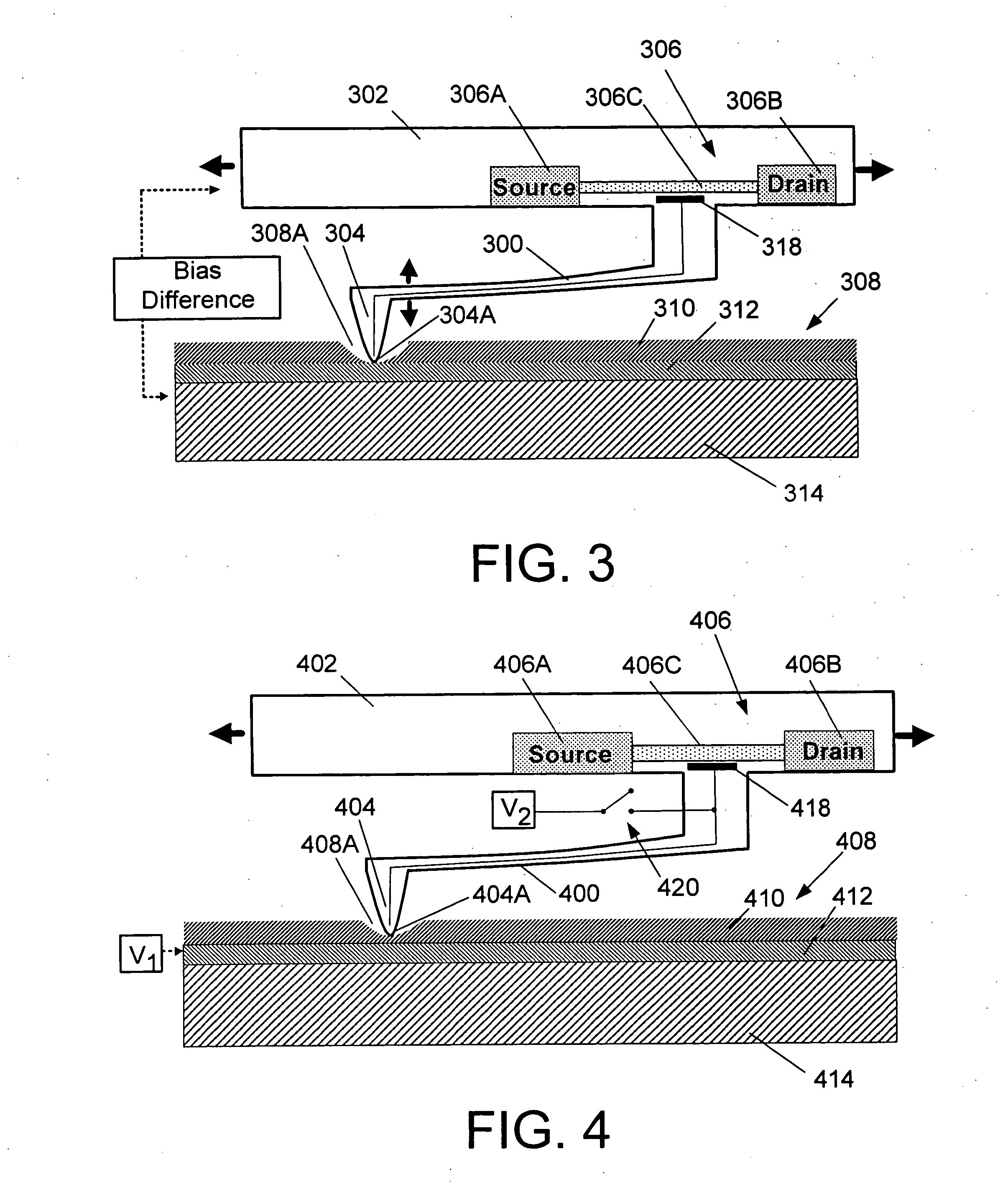
[0034]FIG. 3 shows the invention. In this embodiment, a bias is applied across the substrate 314 which is made of an electrically conductive material, and the chip or base 302.
[0035] Alternatively, in lieu of applying the bias to the substrate 314, a conductive layer can be provided on the substrate 314. This can take the form of an additional layer 312 under one of the polymer layers or the situation wherein one of the polymer layers themselves is conductive, and applying the bias to this layer. This conductive polymer layer can be formed of a conductive polymer such as SU8 which is a near-UV photoresist that is commonly used in MEMS (Microelectromechanical System) fabrication.
[0036] The antenna / gate 318, which can include a conductive antenna that extends along the cantilever or other flexible suspension, floats to a potential that is determined by cantilever / tip position relative to the biases on the substrate 314 of the storage medium and cantilever support chip or base 302. Th...
fourth embodiment
[0037]FIGS. 4 and 5 show the invention. In this embodiment the cantilever / gate 418 is driven to a potential close to that of the storage medium when the probe 404 drops into a recorded pit. V1 is at a potential that, if applied to the FET's gate 418, will either open or close the channel 406C between its source 406A and drain 406B.
[0038] This is assumed to involve a mechanism wherein, when the tip of the probe 404 gets close enough to the conducting layer 412 when it drops into a pit to actually transfer some charge to it. This could occur through “contact”, quantum mechanical tunneling of charge from tip to film (or vice versa), field-emission of electrons from tip to film, or some other form of conduction (e.g. hopping) between tip and film. Alternatively, the tip of the probe 404 does not get close enough to the conducting film for charge transfer to occur, but the capacitive coupling parameter between the probe tip and / or other parts of the flexible suspension and the conductive...
PUM
 Abstract
Description
Claims
Application Information
 - R&D
- Intellectual Property
- Life Sciences
- Materials
- Tech Scout
- Unparalleled Data Quality
- Higher Quality Content
- 60% Fewer Hallucinations
Browse by: Latest US Patents, China's latest patents, Technical Efficacy Thesaurus, Application Domain, Technology Topic, Popular Technical Reports.
© 2025 PatSnap. All rights reserved.Legal|Privacy policy|Modern Slavery Act Transparency Statement|Sitemap|About US| Contact US: help@patsnap.com