
Supression of dark current in a photosensor for imaging

a photosensor and imaging technology, applied in the field of imaging devices, can solve the problems of dark current being detrimental to the operation and performance of the photosensor, hot carriers can get trapped in the available trap sites, etc., and achieve the effect of preventing current generation

Active Publication Date: 2005-07-07
APTINA IMAGING CORP
View PDF12 Cites 18 Cited by
  • Summary
  • Abstract
  • Description
  • Claims
  • Application Information

AI Technical Summary

Benefits of technology

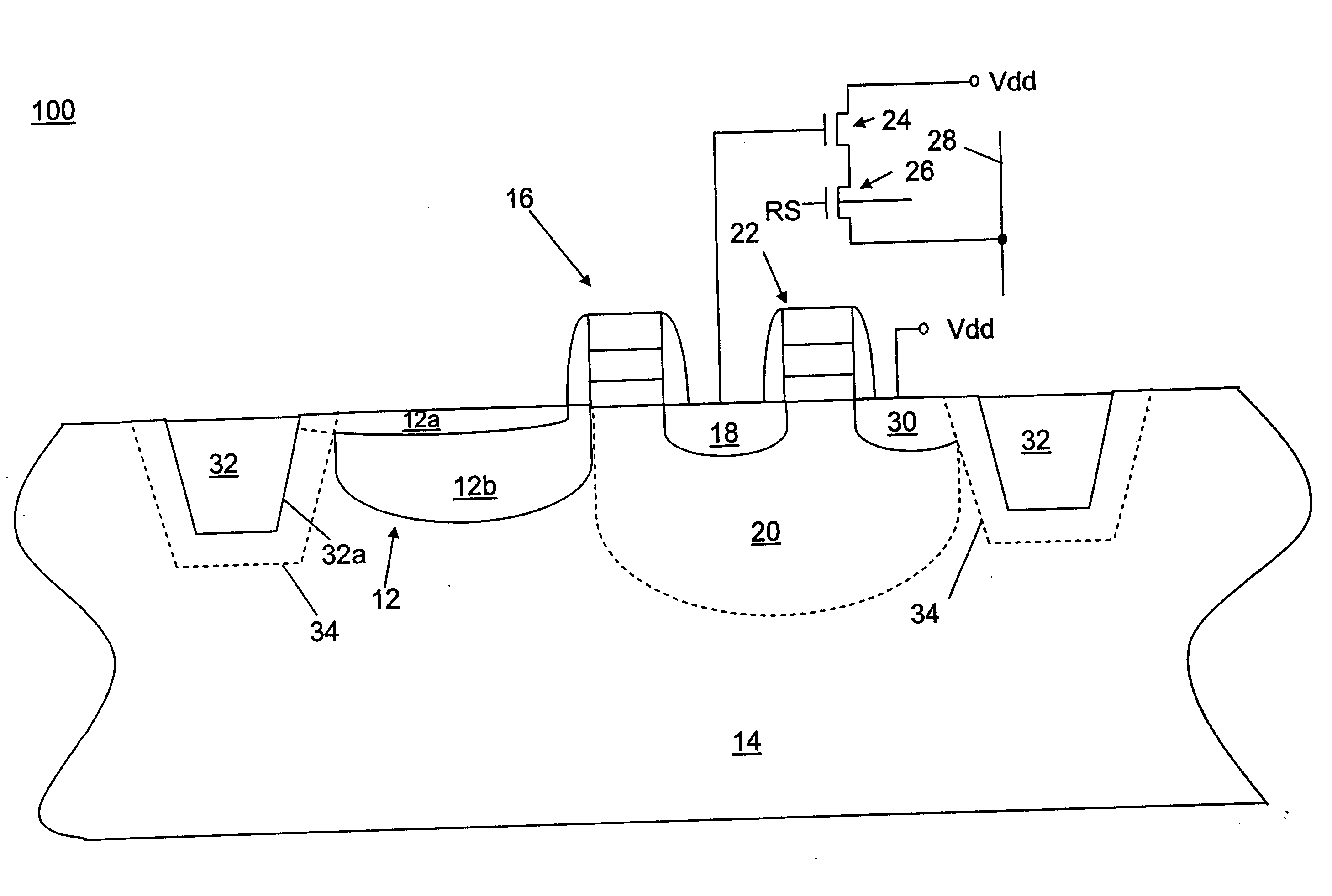
"The present invention provides a way to prevent electrical current and leaks in a pixel cell of an image sensor. This is done by creating a region in the cell that is rich in halogens, which stops the leakage from affecting the photosensor and reducing dark current levels."

Problems solved by technology

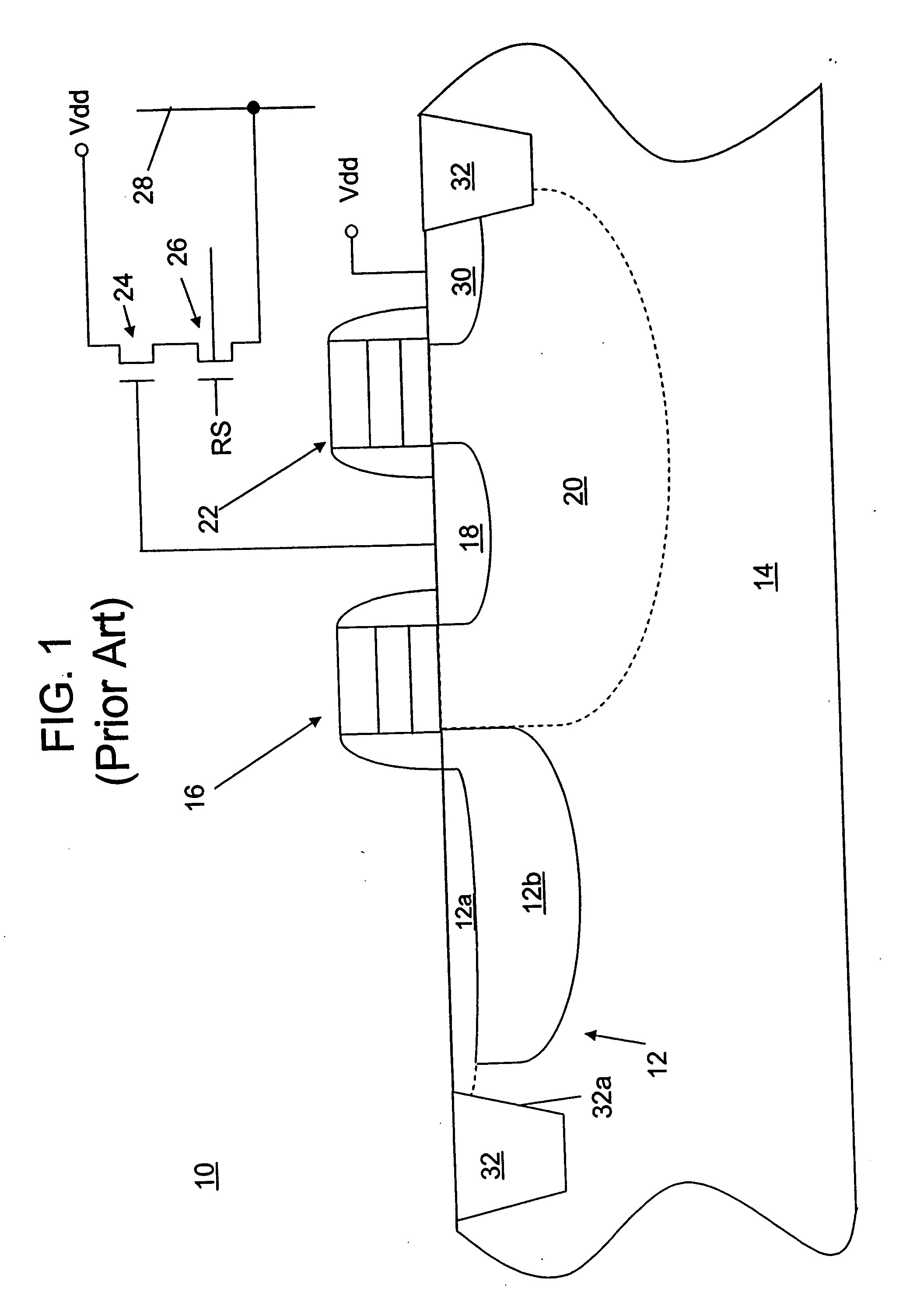
Forming pixel cell 10 between STI regions 32, however, creates problems in the operation of the pixel cell 10.
Hot carriers can get trapped in the available trap sites, and contribute to the fixed charge of the device and change the threshold voltage and other electrical characteristics of the device.
Dark current is detrimental to the operation and performance of a photosensor.

Method used


Image

  • Supression of dark current in a photosensor for imaging
  • Supression of dark current in a photosensor for imaging
  • Supression of dark current in a photosensor for imaging

Examples


Embodiment Construction

[0023] In the following detailed description, reference is made to the accompanying drawings, which form a part hereof and show by way of illustration specific embodiments in which the invention may be practiced. These embodiments are described in sufficient detail to enable those skilled in the art to practice the invention, and it is to be understood that other embodiments may be utilized, and that structural, logical, and electrical changes may be made without departing from the spirit and scope of the present invention. The progression of processing steps described is exemplary of embodiments of the invention; however, the sequence of steps is not limited to that set forth herein and may be changed as is known in the art, with the exception of steps necessarily occurring in a certain order.

[0024] The terms “semiconductor substrate,”“silicon substrate,” and “substrate” are to be understood to include any semiconductor-based structure. The semiconductor structure should be unders...


PUM


Abstract

A pixel cell having a halogen-rich region localized between an oxide isolation region and a photosensor. The halogen-rich region prevents leakage from the isolation region into the photosensor, thereby suppressing dark current in imagers.

Description

FIELD OF THE INVENTION [0001] The present invention relates generally to an imaging device and more specifically to an imaging device pixel cell having a halogen-rich region formed therein, suppressing dark current in a photosensor. BACKGROUND OF THE INVENTION [0002] Imaging devices, including charge-coupled-devices (CCD) and complementary metal oxide semiconductor (CMOS) sensors have commonly been used in photo-imaging applications. [0003] Exemplary CMOS imaging circuits, processing steps thereof, and detailed descriptions of the functions of various CMOS elements of an imaging circuit are described, for example, in U.S. Pat. No. 6,140,630 to Rhodes, U.S. Pat. No. 6,376,868 to Rhodes, U.S. Pat. No. 6,310,366 to Rhodes et al., U.S. Pat. No. 6,326,652 to Rhodes, U.S. Pat. No. 6,204,524 to Rhodes, and U.S. Pat. No. 6,333,205 to Rhodes. The disclosures of each of the forgoing patents are hereby incorporated by reference in their entirety. [0004] An imager, for example, a CMOS imager in...

Claims


Application Information

Patent Timeline
Patent Type & Authority Applications(United States)
IPC IPC(8): H01L27/146H01L27/148
CPCH01L27/146H01L27/14601H01L27/148H01L27/1463H01L27/14689H01L27/14609
Inventor MOULI, CHANDRA
Owner APTINA IMAGING CORP
Learn More