
Subsea process assembly

a technology of process assembly and subsea water, which is applied in the direction of separation process, wellbore/well accessories, liquid degasification, etc., can solve the problems of high field capital expenditure and operational expenditure, reducing the commercial ceiling at which the field can be operated viably, and no longer commercially viable to operate the well. achieve the effect of maximising the potential of this pressure differen

Inactive Publication Date: 2005-07-07
ONESUBSEA IP UK LTD
View PDF16 Cites 72 Cited by
  • Summary
  • Abstract
  • Description
  • Claims
  • Application Information

AI Technical Summary

Benefits of technology

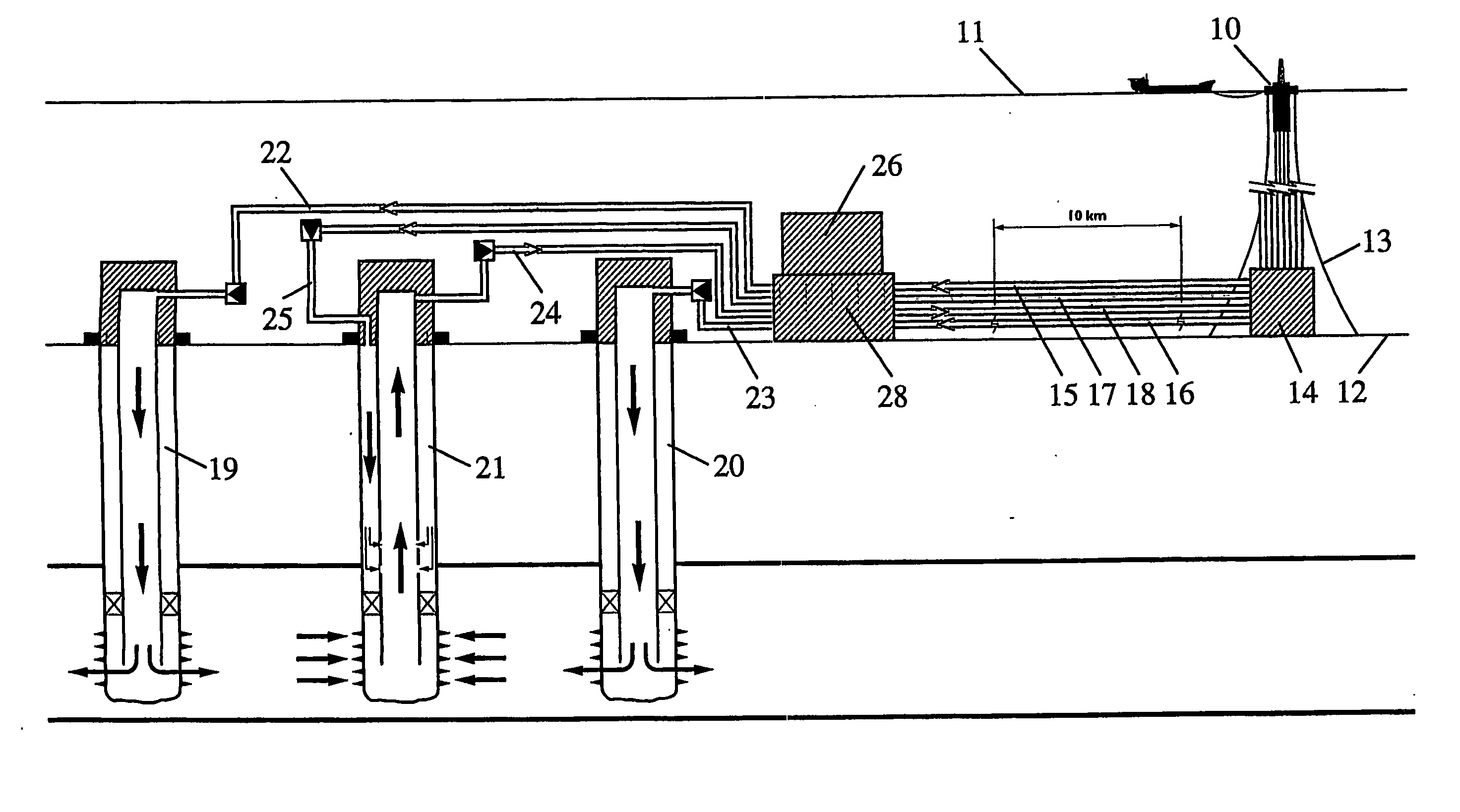
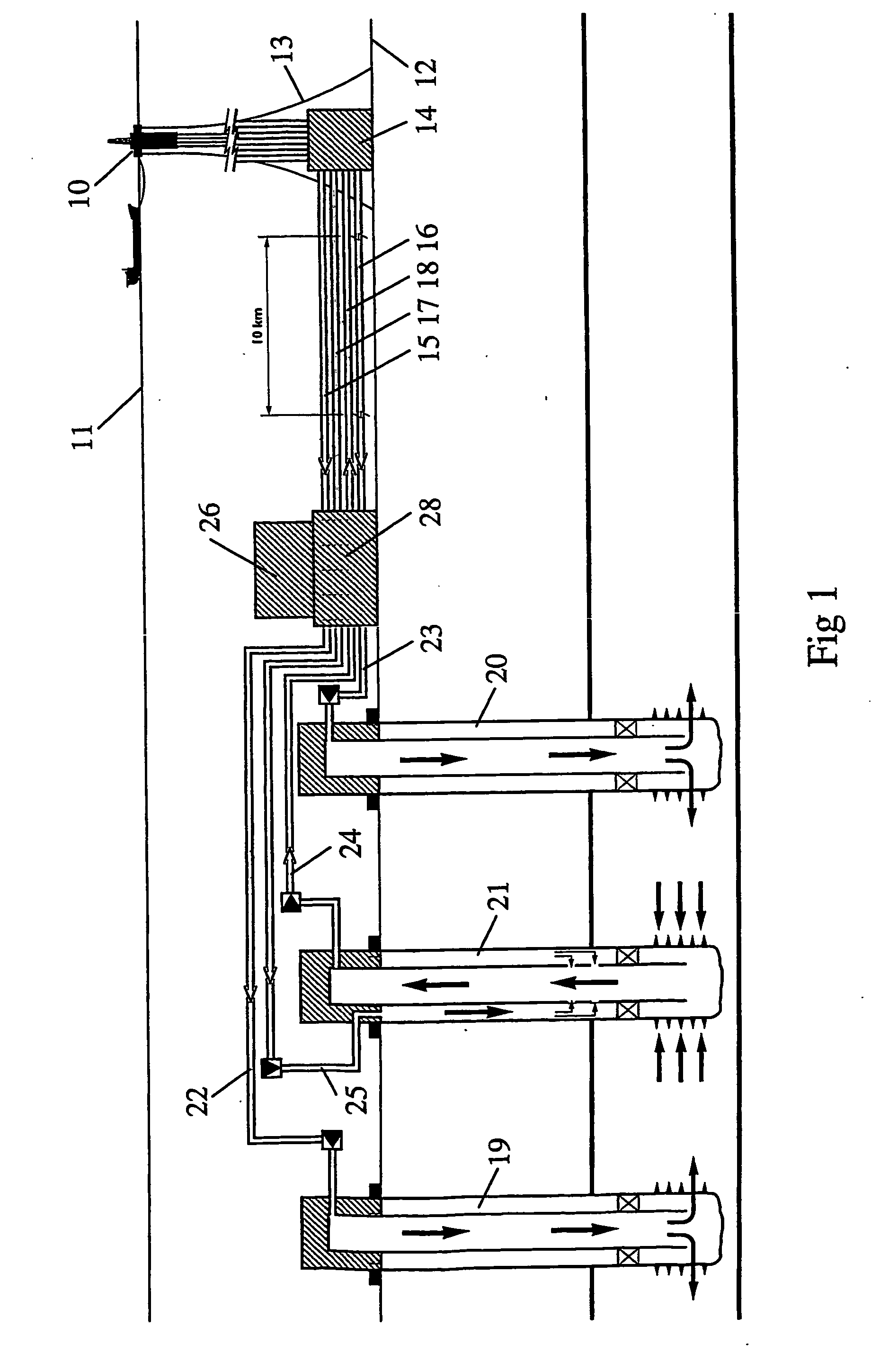
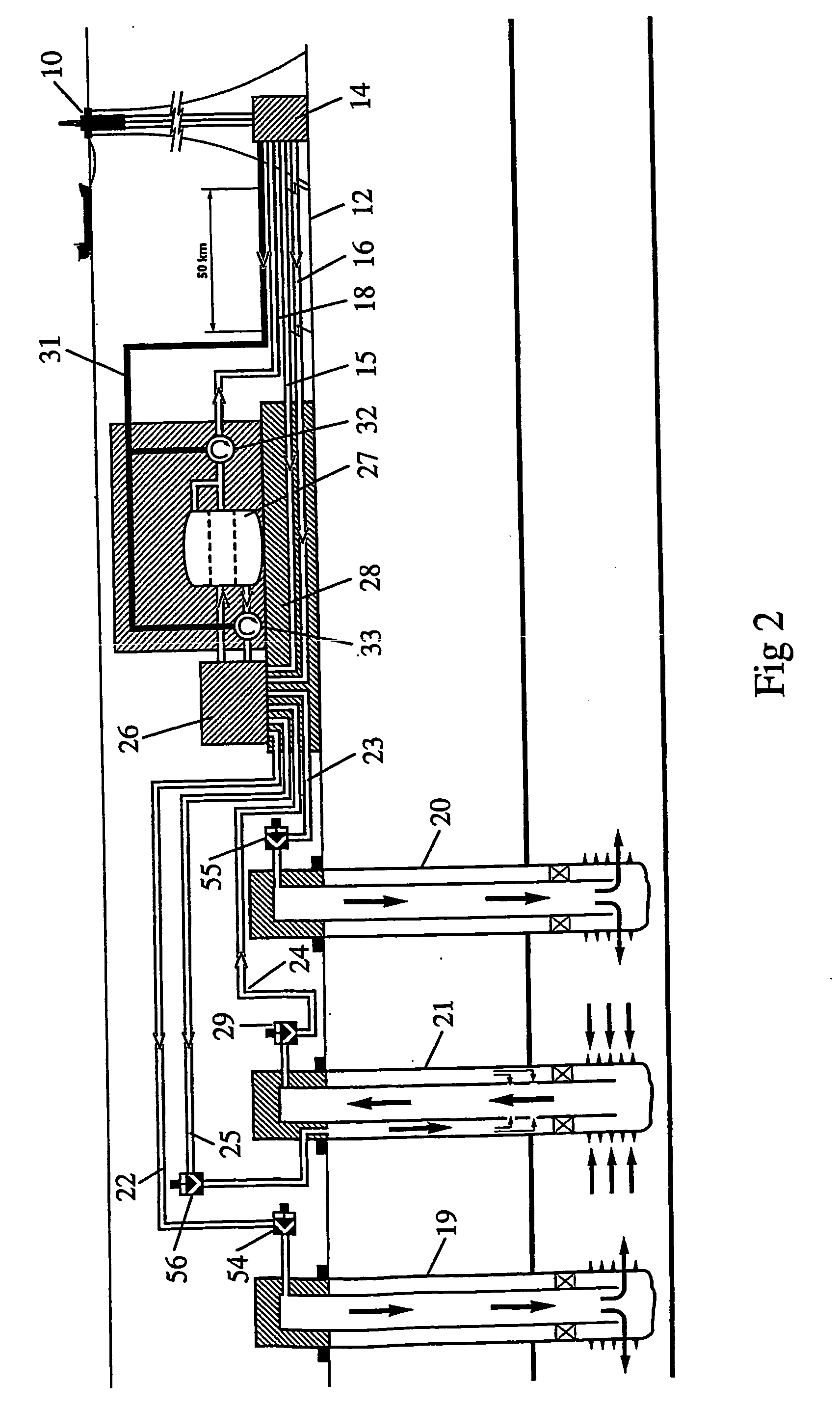
The present invention provides a subsea process assembly for separating a multiphase fluid into individual phases, such as gas, oil, water, and solids. The assembly includes a pressure reducing means for reducing the pressure of the multiphase fluid, a pumping system for pumping the desired individual phases to a delivery point, and a control process module for controlling the pressure reducing means and pumping system. The assembly can be connected to a subsea well for supplying the multiphase fluid. The invention also provides a subsea hydrocarbon recovery system comprising a subsea well, a subsea process assembly, and a delivery point. The system is designed to achieve three phase separation on the seabed and is tailored to suit the production of an individual subsea well. The invention aims to overcome the problems of previous patents and to minimize energy consumption from an external source.

Problems solved by technology

Overall, the current approach requires a complex field production system which has numerous pipelines, thus incurring a high field capital expenditure and operational expenditure.
This high expenditure reduces the commercial ceiling at which the field can be operated viably.
As the field matures and production declines, a level is reached at which considerable resources are left in place but at which it is no longer commercially viable to operate the well.
Back pressure on the well reduces the production rate and brings on an early decline of the wells flowing life as the reservoir pressure at the bottom of the well must overcome the hydrostatic head and the pressure caused by friction.
The input of energy increases the cost of the well, thereby reducing the commercial viability of the well and, in some cases, the entire field.
Accordingly, and especially in deep water, the limited production rates, the early decline and the higher costs result in an increased investment requirement with a lower rate of return.
This ensures that small and medium sized fields cannot be exploited fully, if at all, using current practices.
When wells are at a considerable horizontal distance along the seabed from the surface production vessel, a number of significant problems such as slugging, hydrates, waxing and an increased back pressure are caused by the distance that the production fluid must travel.
In addition, using gas artificial lift in the well can exacerbate these problems causing pipelines to require higher specifications and larger diameters, thereby increasing the cost.
Therefore, a totally pumped field approach has to be taken and pumping has to be installed in some wells that could flow naturally or they need their own pipeline which is very costly.
Accordingly, the pumping requirements add to the conventional field capital expenditure and also increase the operational expenditure of the field.
For commingling to occur, higher and medium pressured wells need to be choked back to the lowest pressure of a commingled well, thereby losing energy from the flow stream.
However, such multiphase pumps require additional energy which increases the cost of this approach.
The requirements for pumping this free gas are very different and, in many cases, opposite to those required for pumping liquid and therefore there is a design conflict and, at best, only a poor compromise can be achieved.
The reason for separating the water from the hydrocarbon is that, when the wells are produced into the system, surface installations need not handle the increased volume of fluid, in particular, caused by the water.
The gravity multiphase separator does not provide energy to the well stream, except by the effect of later allowing the elimination of the hydrostatic head caused by the removal of the partial pressure exert by the water in the multiphase fluid.
This can delay the need for artificial lift, such as gas lift or downhole pumping, and reduces the reliability issues due to the reduction in the downhole complexity.
However, the disadvantage of such a system is that the capital expenditure is extremely high and the complexity of operating such a system are significant.
Once gas has been released, it is slow to be reabsorbed into the liquids and therefore repressuring the gas and injecting it into the liquid line will not prevent separate two phase flow and the forming of slug flows.
Again this time increases as the volume is increased, thereby requiring a large and costly system.
The friction in a horizontal pipeline will cause the pressure in the fluid flow along the pipeline's length to decrease and therefore, even if all of the free gas is removed at the start of the pipeline, a further release of gas will occur along the pipeline due to the pressure drop and this will collect and form a slug, especially in the upper part of an undulation in a pipeline.
Gas breakout in the riser or just prior to the riser base will reduce the density of the fluid and of the hydrostatic head and will therefore cause gas lift in the riser.
For separation of liquids, it is not possible to use differences in pressure changes as this has little effect on the liquid density.
This therefore results in large tanks or a very small throughput of separated fluids.
This has serious limiting factors subsea due to collapse and burst requirements.
Cyclones or a fluid vortex created in a cylinder are effective methods and these reduce the time required for separation but these can only handle a small volume of fluid and at specific parameters.
These do not effect solids in the liquid but will break down the size of liquid droplets, and possibly create an emulsion.
This shows that in the macro field well stream system, energy is lost that has then to be replaced by pumping, and energy has to be provided to pump up the re-injection phases with a considerable amount being lost on the low pressured injection wells.
Currently the tendency is to flow all the produced fluids to the surface installation because of the magnitude of the cost and the ability to operate and control a macro subsea field separation system.

Method used


Image

  • Subsea process assembly
  • Subsea process assembly
  • Subsea process assembly

Examples


Embodiment Construction

[0027] The present invention aims to overcome the problems described above.

[0028] According to the present invention, there is provided a subsea process assembly for separating a multiphase flow, the assembly comprising: [0029] an inlet for a multiphase medium; [0030] a pressure reducing means for reducing the pressure of the multiphase flow from the inlet and creating a source of energy; [0031] a multiphase separator for separating the multiphase input into individual phases; [0032] a pumping system for, in use, pumping at least one of the desired individual phases to a delivery point by utilising at least some of the energy from the source of energy.

[0033] The pumping may be powered by utilising a variable controllable amount of the energy from the source of energy.

[0034] Preferably, the pressure reducing means is coupled to a hydraulic power drive or alternatively to an electric power drive or a flow controller, such as a choke, depending on the optimum method whether hydrauli...


PUM

PropertyMeasurementUnit
pressureaaaaaaaaaa
depthaaaaaaaaaa
pressureaaaaaaaaaa

Abstract

A subsea process assembly for separating a multiphase flow, the assembly comprising: an inlet for a multiphase medium; a pressure reducing means for reducing the pressure of the multiphase flow from the inlet and creating a source of energy; a multiphase separator for separating the multiphase input into individual phases; and a pumping system for, in use, pumping at least one of the desired individual phases to a delivery point by utilizing at least some of the energy from the source of energy.

Description

CROSS-REFERENCE TO RELATED APPLICATION [0001] This application is a National Phase entry of PCT Application No. PCT / GB03 / 01254 filed Mar. 24, 2003 which claims priority to EP Application No. 02252503.4 filed Apr. 8, 2002, both of which are incorporated herein by reference. BACKGROUND OF THE INVENTION [0002] The invention relates to a subsea process assembly which can be used when extracting materials such as hydrocarbons from subsea environments and, in particular, to an assembly which separates a multiphase flow into individual component flows for further supply to specific locations. [0003] In general, the current practice for development of subsea hydrocarbon fields is on a macro field approach which uses a plurality of subsea wells connected through a subsea infrastructure, pipelines and risers to a surface process facility, such as a floating production vessel or a platform. In many locations, especially in remote areas, the proportion of gas and water within the fluid produced...

Claims


Application Information

Patent Timeline
Patent Type & Authority Applications(United States)
IPC IPC(8): B01D17/00B01D17/032B01D17/038B01D17/04B01D17/06B01D19/00B01D21/00E21B43/017E21B43/36E21B43/40
CPCB01D17/00B01D21/2427B01D17/06B01D19/0057B01D21/26E21B43/017E21B43/36E21B43/40B01D17/044B01D21/2411B01D21/10B01D17/0208B01D17/0214B01D17/0217B01D17/12
Inventor HOPPER, HANS PAUL
Owner ONESUBSEA IP UK LTD
Learn More