Driving method of in-plane-switching mode LCD

a technology of in-plane switching and driving method, which is applied in the direction of static indicating devices, non-linear optics, instruments, etc., can solve the problems of not displaying images at a sufficiently high brightness level, and it is difficult for related art lcd panels to effectively display moving pictures

Active Publication Date: 2005-06-30
LG DISPLAY CO LTD
View PDF17 Cites 20 Cited by
  • Summary
  • Abstract
  • Description
  • Claims
  • Application Information

AI Technical Summary

Benefits of technology

[0019] An advantage of the present invention provides a method of driving an LCD panel having a ferroelectric alignment film wherein a rising or falling time required for an LC cell to express light at a predetermined brightness level associated with an applied image signal of a predetermined voltage is reduced by over-driving or under-driving the LC cell for a predetermined amount of time with a compensation voltage.
[0020] Additional features and advantages of the invention will be set forth in the description which follows, and in part will be apparent from the description, or may be learned by practice of the invention. These and other advantages of the invention will be realized and attained by the structure particularly pointed out in the written description and claims hereof as well as the appended drawings.
[0021] To achieve these and other advantages and in accordance with the purpose of the present invention, as embodied and broadly described, a method for driving an LCD panel may, for example, include applying a common voltage to a common electrode of the LCD panel, the LCD panel including a liquid crystal (LC) cell; driving the LC cell to express light at a predetermined brightness level associated with a predetermined data signal voltage applied to a pixel electrode, the driving including applying a compensation voltage to the LC cell prior to applying the predetermined data signal voltage, wherein a voltag...

Problems solved by technology

Related art IPS mode LCD panels can display images over a wide range of viewing angles but do not display images at a sufficiently high brightness levels because the pixel and common electrodes, formed on the same ...

Method used


Image

  • Driving method of in-plane-switching mode LCD
  • Driving method of in-plane-switching mode LCD
  • Driving method of in-plane-switching mode LCD

Examples


first embodiment

[0057]FIG. 6 illustrates waveforms of voltages applied to an IPS mode LCD panel in a driving method according to the present invention.

[0058] Referring to FIG. 6, TFTs within the LCD panel described above with respect to FIGS. 3-5 may be turned on or off in accordance with applied gate voltage. Therefore, when a gate high voltage Vgh of 21V is applied to a gate of a TFT, the gate is opened and the TFT is turned on. Conversely, when a gate low voltage Vgl of −5V is applied to a gate of a TFT, the gate is closed and the TFT is turned off. Further, the common voltage Vcom applied to the common electrode may constitute a uniform DC waveform. Moreover, data signal voltages V2 and V1 may be alternately applied to the pixel electrode of the LC cell in accordance with a driving frequency of the LCD panel. In one aspect of the present invention, the polarity of data signal voltage V2 may be opposite the polarity of data signal voltage V1.

[0059] According to principles of the present inventi...

second embodiment

[0062]FIG. 7 illustrates waveforms of voltages applied to an IPS mode LCD panel in a driving method according to the present invention.

[0063] The waveforms exemplarily illustrated in FIG. 7 may be essentially identical to those illustrated in FIG. 6. However, as shown in FIG. 7, a compensation voltage Vcom′, having the same polarity as the data signal voltage V2, instead of the compensation voltage V1′, may be applied to the common electrode, instead of the data line, for a predetermined amount of time before a second gate-ON period G2. In one aspect of the present invention, the compensation voltage Vcom′ may be applied to the common electrode before the data signal voltage V1 is applied to the data line in accordance with the driving frequency of the LCD panel.

[0064] While the second embodiment does not under drive the LC cell as described above with respect to the first embodiment, the second embodiment effects a reduction in falling time 710 of the LC cell as in the preceding e...

third embodiment

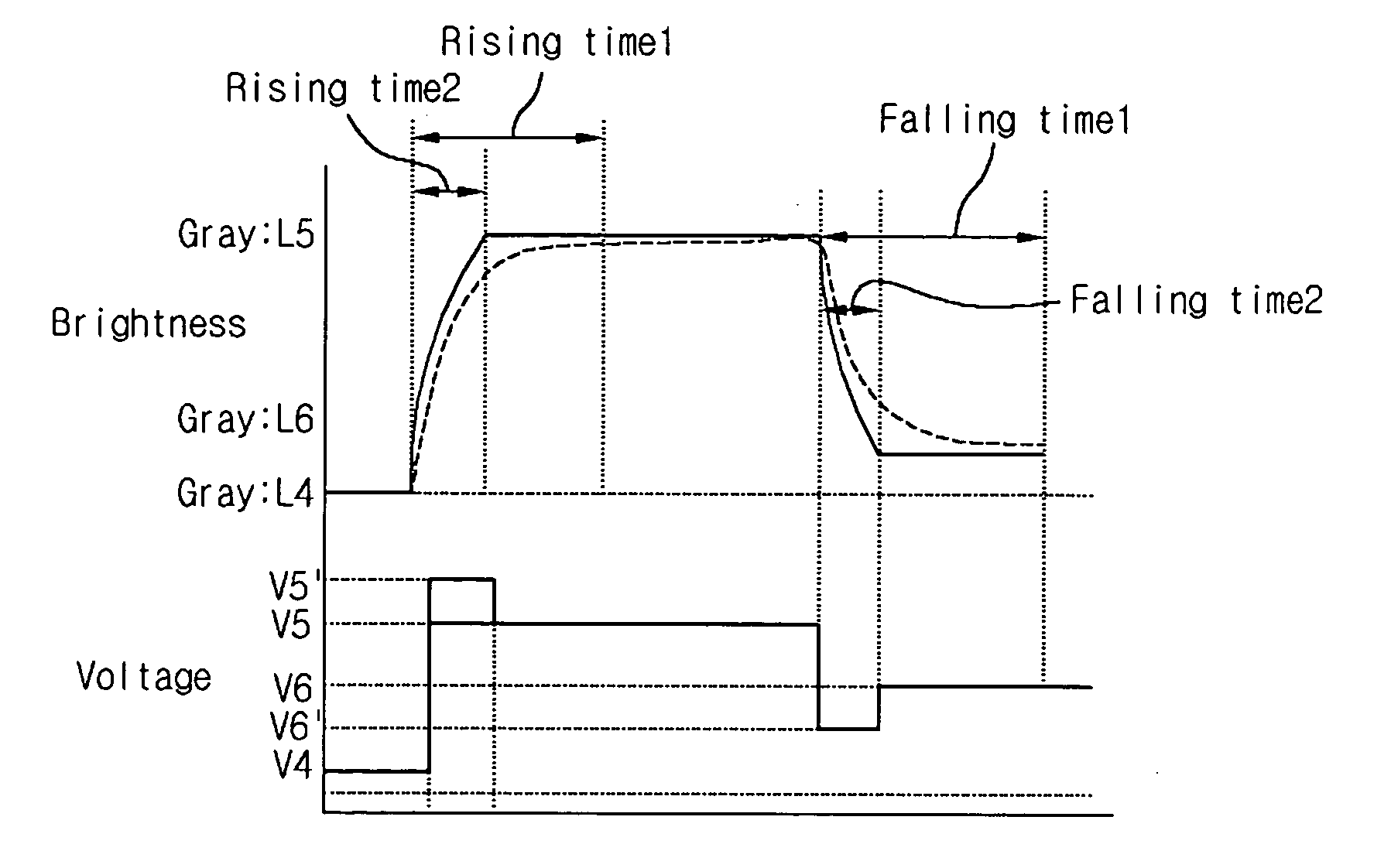
[0066]FIG. 8 illustrates waveforms of voltages applied to an IPS mode LCD panel in a driving method according to the present invention.

[0067] As shown in FIG. 8, the principles of the present invention, outlined above with respect to FIG. 6, may be applied to reduce the response time required to display any gray level.

[0068] For example, the response time required to increase the gray level of an image exhibited by an LC cell from L4 to L5 may be reduced by applying a compensation voltage V5′ having a value greater than a data signal voltage V5, corresponding to the gray level L5. Subsequent to the over-driving, the data signal voltage V5 may be applied to the data line for a predetermined amount of time.

[0069] Further, the response speed required to reduce the gray level of an image exhibited by the LC cell from L5 to L6 may be reduced by applying a compensation voltage V6′ having a value less than a data signal voltage V6, corresponding to gray level L6. Subsequent to the under-...


PUM


Abstract

A method of driving an IPS mode LCD includes applying a common voltage to a common electrode of the LCD panel, the LCD panel including a liquid crystal (LC) cell and driving the LC cell to express light at a predetermined brightness level associated with a predetermined data signal voltage applied to a pixel electrode, the driving including applying a compensation voltage to the LC cell prior to applying the predetermined data signal voltage, wherein a voltage difference between a previously applied data signal voltage and the compensation voltage is greater than a voltage difference between a previously applied data signal voltage and the predetermined data signal voltage.

Description

[0001] This application claims the benefit of Korean Patent Application No. 97382 / 2003, filed on Dec. 26, 2003, which is hereby incorporated by reference for all purposes as if fully set forth herein. BACKGROUND OF THE INVENTION [0002] 1. Field of the Invention [0003] The present invention relates to liquid crystal display (LCD) devices. More particularly, the present invention relates to a driving method of an In-Plane Switching (IPS) mode LCD panel having a ferroelectric alignment film. [0004] 2. Discussion of the Related Art [0005] Generally, LCD panels include a layer of liquid crystal material interposed between two glass substrates. Depending upon their construction and operation, LCD panels can be classified as Twisted Nematic (TN) mode LCD panels or In-Plane Switching (IPS) mode LCD panels. [0006] TN mode LCD panels operate according to a perpendicular movement of liquid crystal molecules with respect to a substrate and include a transparent pixel electrode formed on a surfa...

Claims


Application Information

Patent Timeline
IPC IPC(8): G02F1/133G09G3/20G09G3/36
CPCG09G3/3651G09G3/3688G09G2320/0276G09G2310/0251G09G2300/0434G02F1/133
Inventor JANG, SANG MINCHOI, SU SEOK
Owner LG DISPLAY CO LTD
Why Eureka
Try Eureka