
Determination of physical qualities of lubricant

a technology of physical qualities and lubricant, applied in the measurement of optical radiation, photosensitive materials, instruments, etc., can solve the problems of not being able to monitor the thickness of lubricant longer and the thickness of lubricant is not uniform across the entire disk surfa

Inactive Publication Date: 2005-06-23
HDI INSTR
View PDF8 Cites 22 Cited by
  • Summary
  • Abstract
  • Description
  • Claims
  • Application Information

AI Technical Summary

Benefits of technology

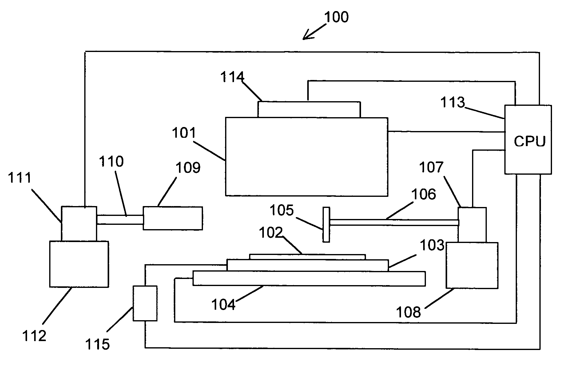
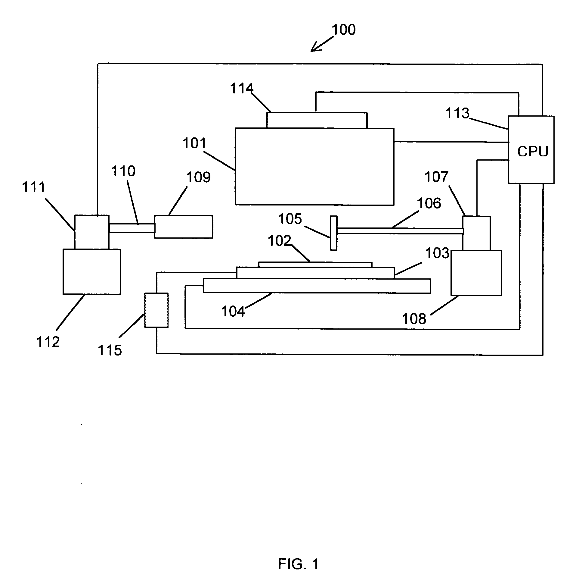
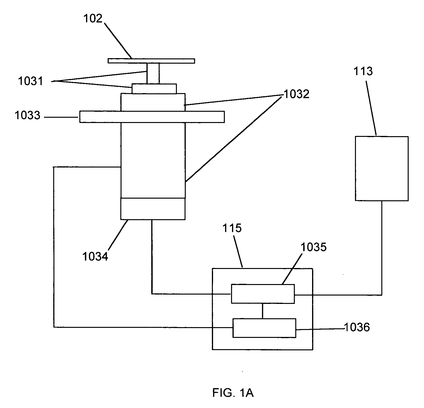
[0008] The lubricant uniformity mapping system includes the optics with high sensitivity to lubricant thickness and an ability to examine a large field of view, i.e., the entire disk surface. The optics analyzes characteristics such as intensity and polarization of the reflected light. The lubricant uniformity mapping system also includes a programmable dispenser / titrator for pumping a lubricant solvent onto the disk. The lubricant system further includes an automatic shutter system to protect the optics from the contamination of the spun-off solvent from the disk during a de-lubricating process. Although not required for the operation of this system, the lubricant uniformity mapping system may also use a collet chuck for protecting the air bearing spindle used during the de-lubrication step from contamination by the solvent during de-lubricating.
[0010] An object of the present invention is to provide a method and apparatus in which the lubricant uniformity map of a finished disk can be generated automatically.

Problems solved by technology

For the disk lubrication process it is no longer enough to monitor the lubricant thickness on a single point on the disk surface.
The lubricant, which for example, may be put on the disk in a dip process or using alternative processes with the result that the lubricant thickness is not uniform across the entire disk surface.

Method used


Image

  • Determination of physical qualities of lubricant
  • Determination of physical qualities of lubricant
  • Determination of physical qualities of lubricant

Examples


second embodiment

[0032] the dispenser / titrator 400 is shown in FIG. 4. It is a peristaltic pump style dispenser / titrator. A peristaltic pump head 403 driven by a motor 401 though an interface 402 pumps the solvent 408 from the bottle 406 to a nozzle 405 through both inlet and outlet tubings 404. The dispensing volume and flow rate are controlled by either a control panel 409 manually or a PC or CPU 410 through an RS-232 serial port.

third embodiment

[0033] the dispenser / titrator 500 is shown in FIG. 5. It is an air driven style dispenser / titrator. When the pure air is blown into the sealed bottle 505 through an inlet tubing 503, the solvent 506 is pushed out of the bottle 505 to the nozzle 504 through the outlet tubing 507. The dispensing flow rate is set by the air regulator 501, and the dispensing volume is controlled by the electronic valve 502.

first embodiment

[0034] the automatic shutter system 600 is shown in FIG. 6. It is a rotary shutter system. The shutter 604 supported by an arm 603 is driven by a rotary actuator 601, like a SMC Pneumatics, Inc's MDSUB1-90S-90, through a shaft 602. The rotary actuator 601 could be a pneumatic turntable or a motor, such as a stepper motor, a servomotor, an ultrasonic motor, or a piezoelectric motor. The actuator 601 is mounted on a base 605. A PC or CPU 606 controls the actuator 601 to rotate the shutter 604 up and down about 90 degree along the shaft 602. The position of the shutter is determined by built-in position sensors mounted on the shaft 602 that detect the angular position of the shaft at some pre-set positions, like 0 degree or 90 degrees to the horizontal direction, or a built-in rotary encoder mounted on the shaft 602 that measures the angular position of the shaft. The position of the shutter also can be determined by separate position sensors 607 and 608. These position sensors can be ...


PUM

PropertyMeasurementUnit
thicknessaaaaaaaaaa
speedaaaaaaaaaa
optical instrumentationaaaaaaaaaa

Abstract

A method and apparatus for the mapping, measurement, and determination of the layer of lubrication on the surface of hard magnetic disks. This is achieved through the use of measurements made with optical instrumentation capable of making a number of measurements based on illuminating the hard disk surface with polarized light which is specularly reflected, analyzed, and recorded. An initial measurement is made of the surface layer of lubricant and then the lubricant is removed and another measurement is made of the surface of the disk. The second scan is then subtracted from the first scan to provide a representation of the lubricant layer.

Description

FIELD OF THE INVENTION [0001] The present invention relates to the measurement of the lubricant layer and its uniformity as present on magnetic recording disks. BACKGROUND OF THE INVENTION [0002] Personal computer systems use hard disk drives as the preferred information storage device. To read and write on such drives, a recording head is made to fly above the surface of the disk, while the disk is spinning, and in close proximity thereto. A typical disk has a carbon overcoat sputtered on the surface of magnetic media. To protect the disk surface from contact with the recording head (and the recording head from contact with the disk surface), a fluorinated lubricant such as perfluoropolyether (PFPE) is placed on top of the disk surface. Different techniques for placing a lubricant on the disk may be found, for example, in U.S. Pat. No. 5,232,503 and also in U.S. Pat. No. 6,183,831. Disk tribology and durability are highly dependent on the properties of this lubricant so that the de...

Claims


Application Information

Patent Timeline
Patent Type & Authority Applications(United States)
IPC IPC(8): B05C11/00G01J1/42G01N21/21G03D5/00
CPCG01N21/21
Inventor LENG, QINGFANGKHAZENI, KASRA
Owner HDI INSTR
Learn More