Ultra-high speed vacuum pump system with first stage turbofan and second stage turbomolecular pump

a vacuum pump and ultra-high-speed technology, which is applied in the field of vacuum pumps, can solve the problems of low axial force exerted on the rotor, and achieve the effect of simple bearing components

Inactive Publication Date: 2005-06-16
FERMI RESEARCH ALLIANCE LLC
View PDF49 Cites 6 Cited by
  • Summary
  • Abstract
  • Description
  • Claims
  • Application Information

AI Technical Summary

Benefits of technology

[0023] The rotor blades of the present turbofan are capable of rotating at a high linear blade velocity, to impart an ultra high pumping speed to a fluid stream, while remaining stabilized and without requiring a large power source for blade operation.
[0024] The present turbofan is preferably employed in a preexisting low pressure environment. In such an environment it is believed that this results in low axial forces exerted upon the rotors from the flu

Problems solved by technology

In such an environment it is believed that this results in low axial

Method used


Image

  • Ultra-high speed vacuum pump system with first stage turbofan and second stage turbomolecular pump
  • Ultra-high speed vacuum pump system with first stage turbofan and second stage turbomolecular pump
  • Ultra-high speed vacuum pump system with first stage turbofan and second stage turbomolecular pump

Examples


Embodiment Construction

)

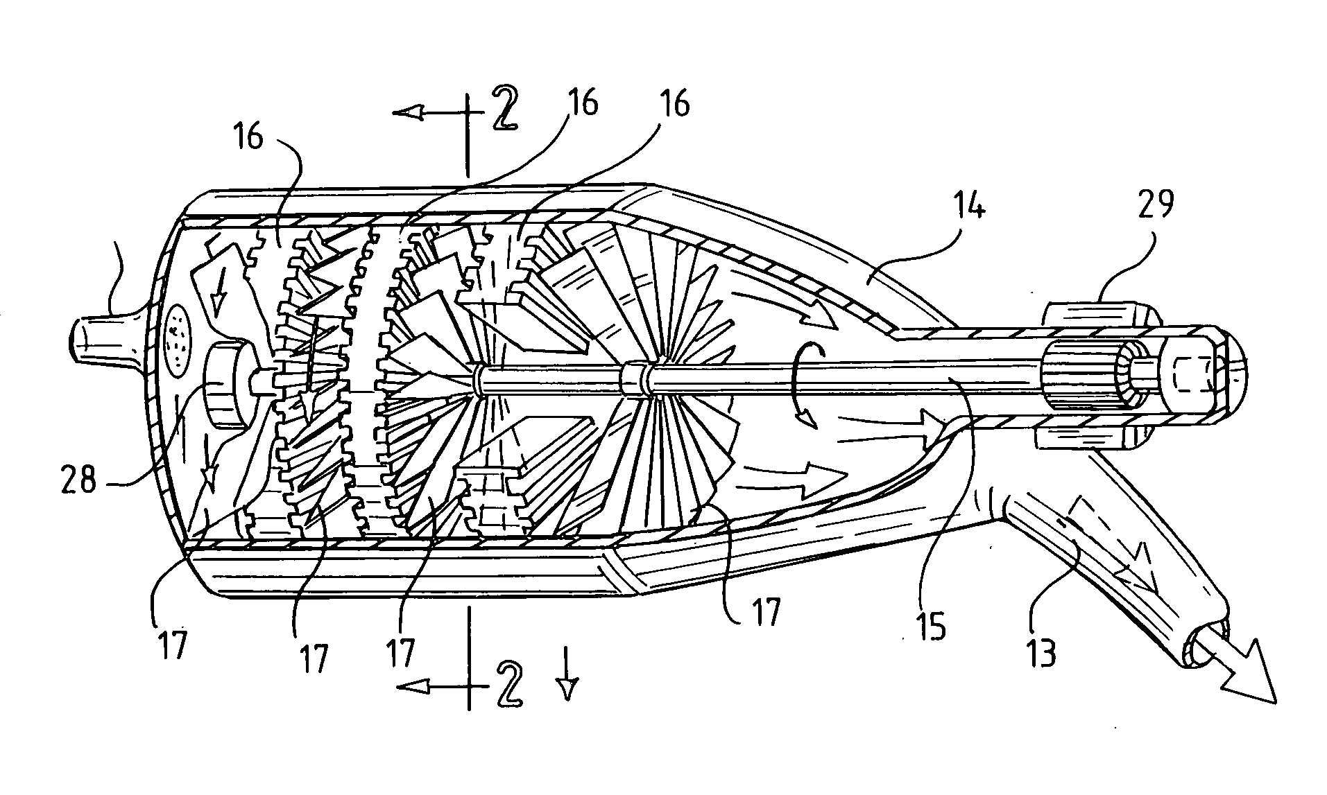
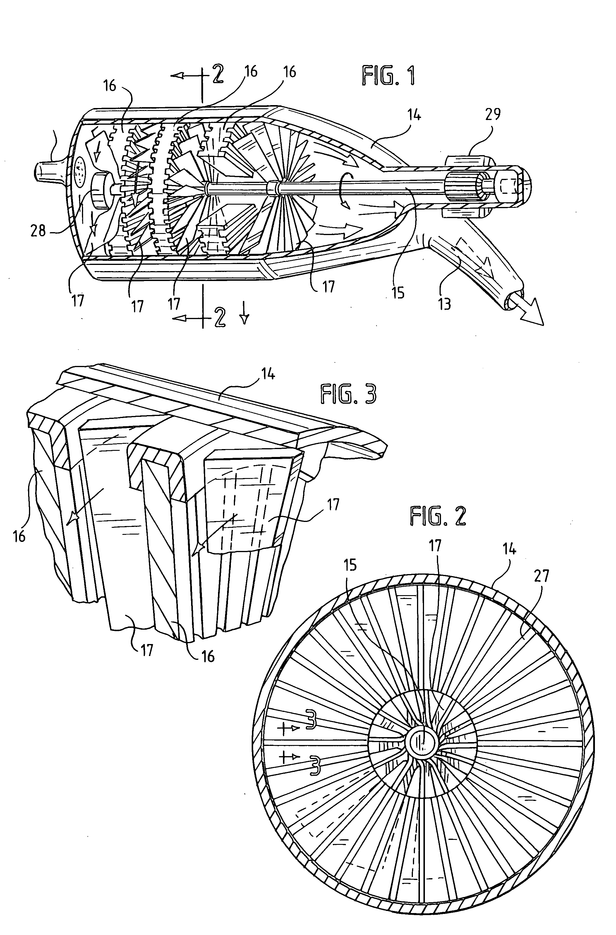
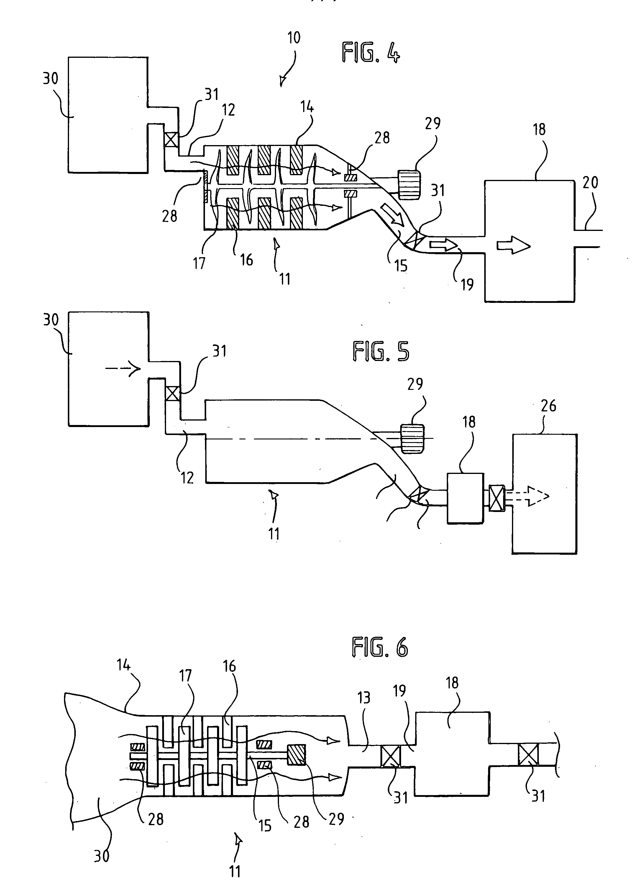
[0038] Shown in FIG. 1 of the drawings is one embodiment of an ultra high speed vacuum pump turbofan 11, which is preferably employed as an ultra-high speed input stage, backed by a conventional turbomolecular pump. Turbofan 11 acts to draw a fluid stream into a turbofan inlet 12 and through to a turbofan outlet 13. Preferably, this outlet fluidly communicates with at least one additional turbofan or turbomolecular pump, as shown in FIG. 4 and FIG. 5. Also preferably, the Turbofan inlet 12 fluidly communicates with an evacuation or process chamber 30, as shown in FIG. 4 and FIG. 5. Turbofan 11 is characterized by a ultra high pumping speed and moderate compression ratios.

[0039] Typical pumping speeds are greater than 10,000 liters / second. More preferably, the pumping speeds are from 10,000 liters / second to 40,000 liters / second. In a preferred embodiment, turbofan 11 has a pumping speed of about 25,000 liters / second for a 1.0 meter diameter turbofan.

[0040] Turbofan 11 need only ha...


PUM


Abstract

An ultra-high speed vacuum pump evacuation system includes a first stage ultra-high speed turbofan and a second stage conventional turbomolecular pump. The turbofan is either connected in series to a chamber to be evacuated, or is optionally disposed entirely within the chamber. The turbofan employs large diameter rotor blades operating at high linear blade velocity to impart an ultra-high pumping speed to a fluid. The second stage turbomolecular pump is fluidly connected downstream from the first stage turbofan. In operation, the first stage turbofan operates in a pre-existing vacuum, with the fluid asserting only small axial forces upon the rotor blades. The turbofan imparts a velocity to fluid particles towards an outlet at a high volume rate, but moderate compression ratio. The second stage conventional turbomolecular pump then compresses the fluid to pressures for evacuation by a roughing pump.

Description

[0001] This invention was made with Government support under Contract No. DE-AC02-76CH03000, awarded by the United States Department of Energy. The Government has certain rights in the invention.FIELD OF THE INVENTION [0002] The present invention relates to vacuum pumps for generating ultra-high vacuum within an evacuated chamber. More specifically, the present invention relates to a vacuum pump systems that include a first stage high-speed turbofan and a second stage turbomolecular pump, as well as a method of using the vacuum pump system. BACKGROUND OF THE INVENTION [0003] Turbomolecular pumps (TMPs; sometimes also referred to as turbopumps) are widely employed for generating an ultra-high vacuum in an evacuated chamber. Vacuum pumps generally include turbo molecular pumps, drag pumps, centrifugal pumps, diffusion pumps, cryopumps, titanium sputter pumps, getter pumps and the like. In general, turbomolecular pumps are employed to compress gases, such as hydrogen in the 10−8 Pa (10...

Claims


Application Information

Patent Timeline
IPC IPC(8): F04D19/04F04D29/056F04D29/048
CPCF04D19/046F04D19/042
Inventor JOSTLEIN, HANS
Owner FERMI RESEARCH ALLIANCE LLC
Why Eureka
Try Eureka