
Striking tool for comminuting materials

a technology of comminuting materials and striking tools, which is applied in the field of striking tools, can solve the problems of insufficient strike-proof and wear-proof, and achieve the effect of preventing the jamming of the striking tool

Inactive Publication Date: 2005-06-16
BETEK BERGBAU UND HARTMETALLTECHN KARL HEINZ SIMON
View PDF1 Cites 0 Cited by
  • Summary
  • Abstract
  • Description
  • Claims
  • Application Information

AI Technical Summary

Benefits of technology

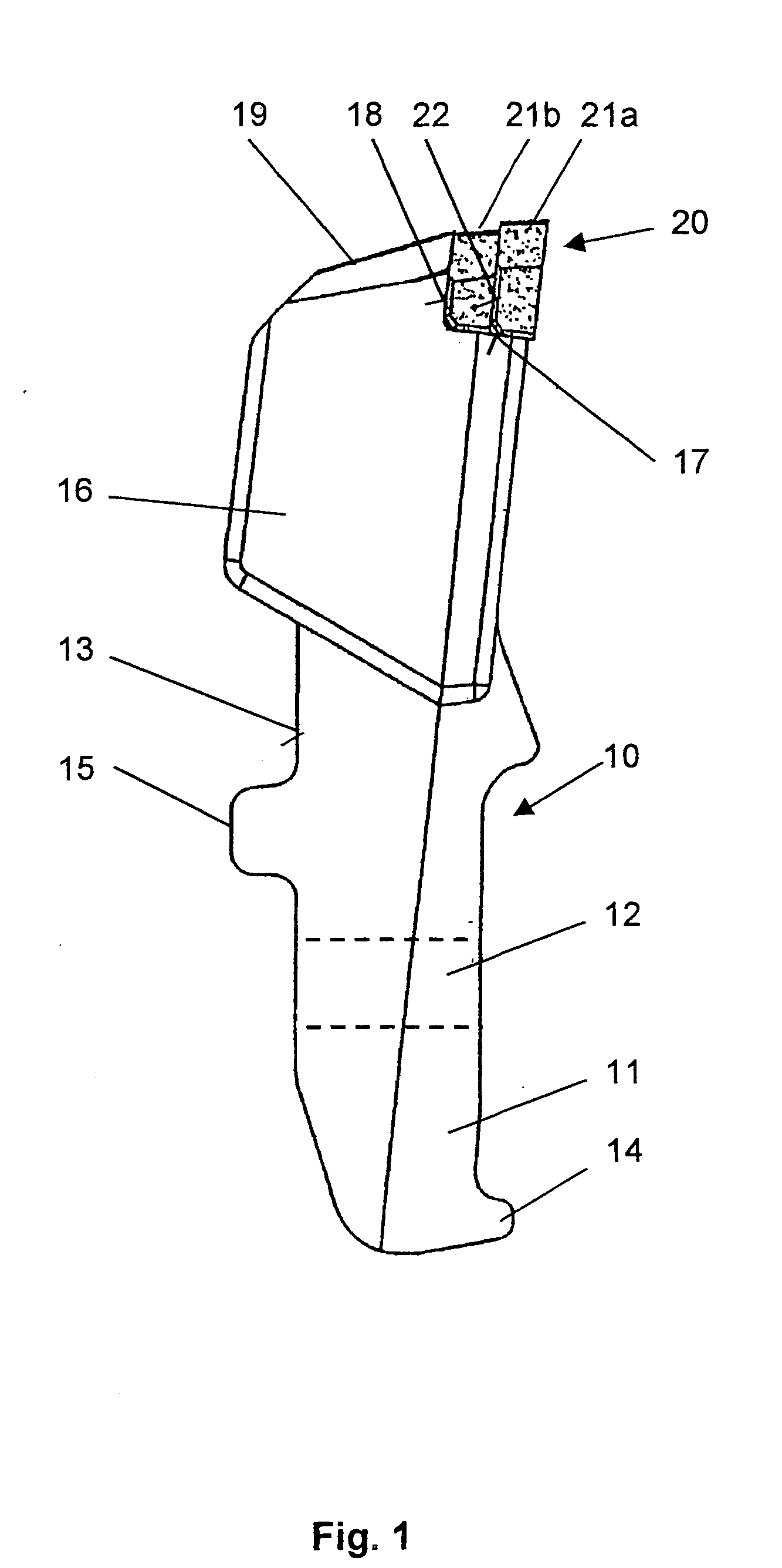
[0008] It is one object of this invention to provide a striking tool of the type mentioned above but which has an extended service life, along with improved comminution output.
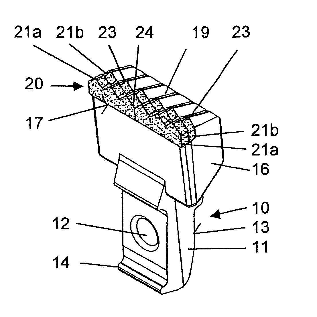
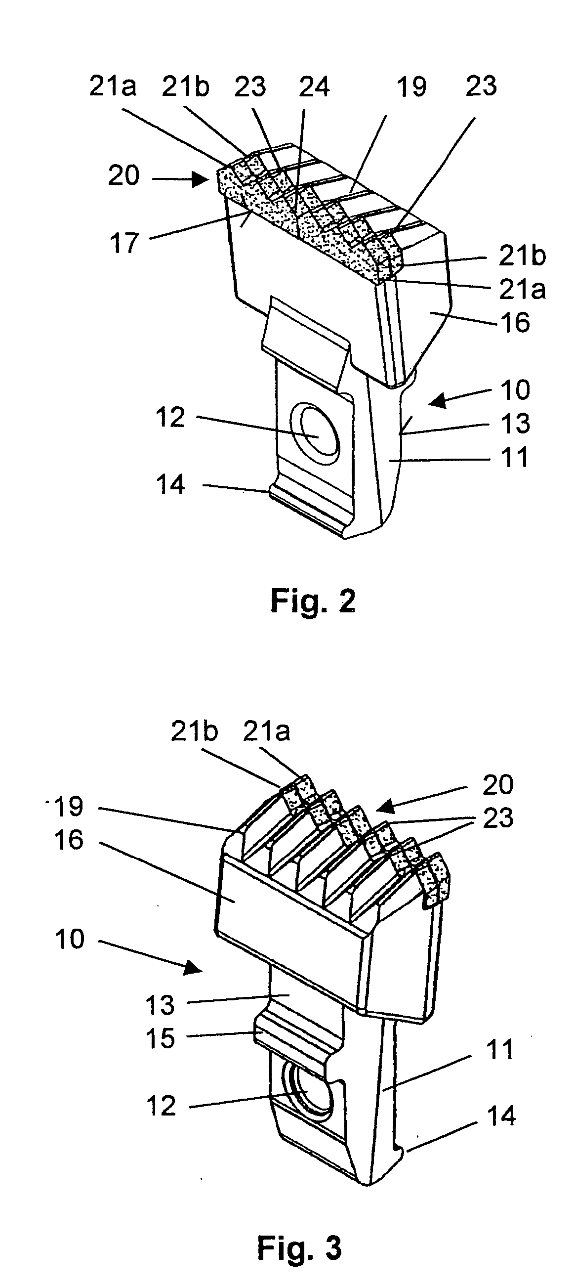
[0010] The cutting insert is preferably constructed so that it has two or several first and / or second cutting elements, which are arranged side-by-side transversely with respect to a cutting direction. As a result of the reduced size thus caused, the bending strain on the individual elements is reduced during operations, which leads to a reduced loss because of breaking. Also, with the loss of a cutting element the adjoining elements continue to be available.
[0011] If the first and / or the second cutting elements are plate-shaped and have one or more teeth arranged side-by-side transversely with respect to the cutting direction, an improved chip-cutting of fiber-containing materials, such as wood, is achieved.
[0013] A lasting and dimensionally stable holding of the cutting element of the cutting insert on the chisel head is achieved because the chisel head has a receiver for the cutting insert, which has two support surfaces extending at an angle with respect to each other. The first support surface substantially extends in the cutting direction. The first and second cutting elements are supported on this support surface. The second cutting element, which is arranged behind the first cutting element in the cutting direction, is supported with its back at the second support surface, and the back of the first cutting element is supported at the front of the second cutting element.
[0015] A dimensionally stable support of the cutting device, along with the simultaneous prevention of jamming of the striking tool, is achieved because the chisel head has a free surface which is inclined with respect to the cutting direction and adjoins the cutting insert opposite to the cutting direction. The first cutting element makes a transition via the second cutting element into the free surface.

Problems solved by technology

In case of breaking or loss of one of the front cutting elements, which are mainly exposed to the striking stresses, a cutting element arranged behind it is available, which takes on the cutting work, as well as the mechanical protection of the chisel head located behind it, which is insufficiently strike-proof and wear-proof.

Method used


Image

  • Striking tool for comminuting materials
  • Striking tool for comminuting materials
  • Striking tool for comminuting materials

Examples


Embodiment Construction

[0020]FIG. 1 shows a striking tool 10 with a shank 11 and a chisel head 16 connected with the shank 11, in a lateral view. The striking tool 10 is fastened by a bolt, not shown, which is guided through a fastening bore 12, on a rotating beater, also not shown. Besides the bolt, protrusions 14, 15 are used for the releasable holding of the striking tool 10 on the beater and for the transmission of the forces occurring during operations. A clamping surface 13 is also used for transferring the forces to the beater. The chisel head 16 connected with the shank 11 supports a cutting insert 20, which is composed of the cutting elements 21a and 21b, which are located one behind the other in the working direction. The rear cutting element 21b is connected at a rear portion with the chisel head 16 via a support surface 16, and at an underside via a support surface 17, for example soldered together and can be made of a material of reduced quality with respect to the front cutting element 21a, ...


PUM


Abstract

A striking tool for comminuting materials, particularly waste wood, having a shank and a chisel head, wherein a cutting insert is fastened on the chisel head. For an extended service life, along with an improved comminuting output, the cutting insert has at least one first and at least one second cutting element and the first and second cutting elements are arranged one behind the other in the cutting direction.

Description

BACKGROUND OF THE INVENTION [0001] 1. Field of the Invention [0002] This invention relates to a striking tool, for comminuting materials such as waste wood, having a shank and a chisel head, wherein a cutting insert is fastened on the chisel head. [0003] 2. Discussion of Related Art [0004] A striking tool taught by German Patent Reference DE 35 45 708 C2 has a revolving beater to whose base body a releasably connected cutting body is attached. The cutting body is designed as a tooth with a shank. In this case the shank has a cutting head, which generally protrudes in a longitudinal direction out of a cutout of the base body seated so that it can be pivoted in, and has a substantially triangular cross section defining the cutting edge. A predetermined breaking point is defined by a cutout of triangular cross section in the front face of the cutting head, viewed in the circumferential direction, at which the cutting head breaks at a predetermined location in case of an overload, for e...

Claims


Application Information

Patent Timeline
Patent Type & Authority Applications(United States)
IPC IPC(8): B02C13/28B02C18/18
CPCB02C18/18B02C13/28
Inventor KAMMERER, KARL
Owner BETEK BERGBAU UND HARTMETALLTECHN KARL HEINZ SIMON
Learn More