
Solar cell

a solar cell and cell technology, applied in the field of solar cells, can solve the problems of increasing the price of solar cells, increasing power loss, and no longer being able to supply stable electrical power, and achieve the effect of stable electrical power

Inactive Publication Date: 2005-06-16
THE FUJIKURA CABLE WORKS LTD
View PDF7 Cites 42 Cited by
  • Summary
  • Abstract
  • Description
  • Claims
  • Application Information

AI Technical Summary

Benefits of technology

[0011] The present invention provides a power generation apparatus including a solar cell that also functions as a capacitor or a secondary cell and is capable of providing a stable electrical power using the solar cell.

Problems solved by technology

As a result, a stable supply of electrical power will be no longer available.
However, addition of such a device external to a solar cell may cause an increase in power loss caused by resistance and the like, and a solar cell can only supply a power as low as a value lower than the actual power generation capacity of the solar cell.
Furthermore, addition of an external device may increase the price of the solar cell since the structure of a solar cell and a power generation apparatus using a solar cell may become complex.
This method is not a viable option when a low-cost photovoltaic power generation apparatus is desired.
However, such a technique may make the whole system complex, and may decrease generation efficiency and increase price.

Method used


Image

  • Solar cell
  • Solar cell
  • Solar cell

Examples


example 1

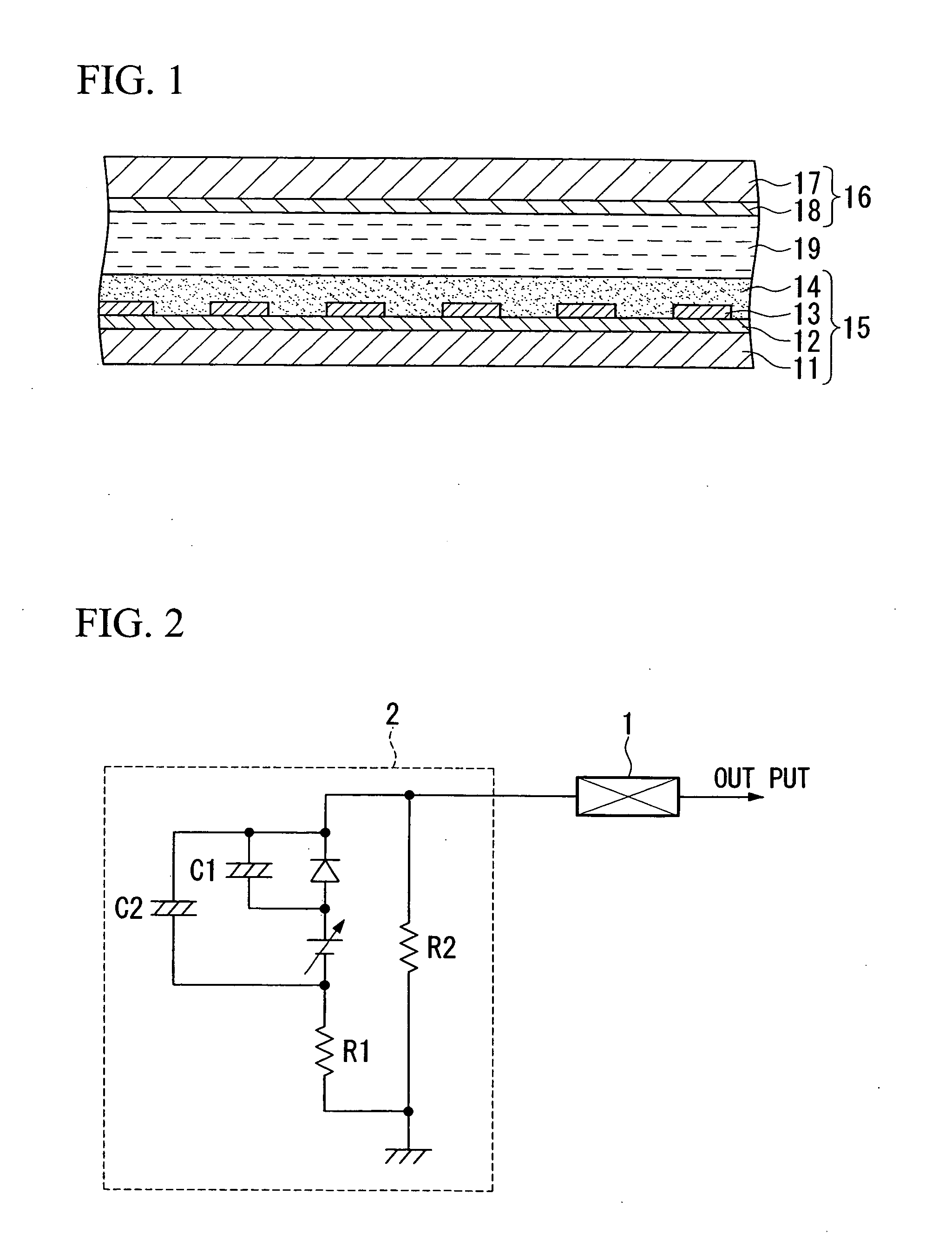
[0067] A transparent electrically conductive film made of FTO was formed on a transparent glass substrate with a size of ten centimeters square, and mesh-like current collecting wirings having 90% of an open area ratio were formed on the transparent electrically conductive film using a sintered-type silver paste. After a porous semiconductor film made of titanium oxide was formed as a protective layer of the wirings on the current collecting wirings, titania nanoparticle paste was coated on the porous semiconductor film and sintered. Then, the porous semiconductor film was dipped into a dye solution to sensitize the porous semiconductor film with the dye, and the porous semiconductor film was dried at room temperature to form a dye sensitized porous semiconductor film. The dye sensitized porous semiconductor film was used as a working electrode.

[0068] In addition, a counter electrode was made by forming a staked body having a conductive film which is formed by sputtering platinum o...

example 2

[0071] A cell was fabricated in a manner similar to that of Example 1, except that an iodine-based electrolyte was prepared by dissolving silver powders until they were saturated, and the current collecting wirings were not formed on the transparent electrically conductive film.

example 3

[0072] A cell was fabricated in a manner similar to that of Example 1, except that an iodine-based electrolyte was prepared by dissolving nickel powders until they were saturated, and the current collecting wirings were not formed on the transparent electrically conductive film.


PUM


Abstract

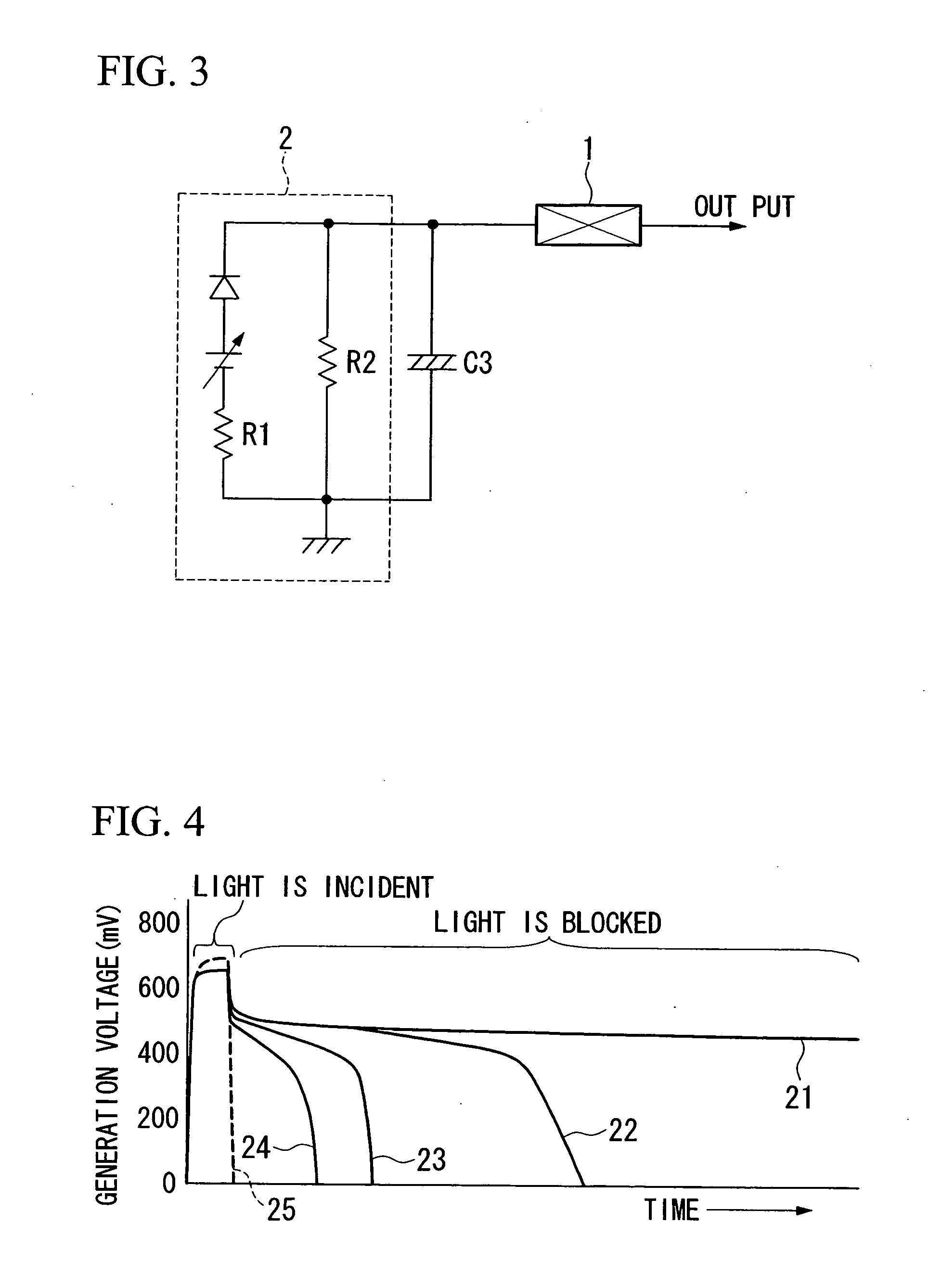
A solar cell and photovoltaic power generation apparatus including a transparent electrically conductive film, a semiconductor provided on the transparent electrically conductive film, a conductive film opposing the semiconductor, and an electrolyte solution filled between the semiconductor and the conductive film. Metal ions, such as silver ions, may be dissolved in the electrolyte solution. When light is incident on the cell, the metal ions cause an oxidation-reduction reaction in the electrolyte solution and the cell is charged. When the open-circuit voltage decreases because the amount of incident light drops or light is blocked, the cell discharges to function as a secondary cell.

Description

[0001] This application is based upon and claims the benefit of priority from International Application PCT / JP2003 / 008653 which is based on Japanese Patent Application No. 2002-199958, filed in Japan on Jul. 9, 2002, the disclosure of which is incorporated herein by reference.TECHNICAL FIELD [0002] The present invention relates to a solar cell that increases stability of the output voltage (open-circuit voltage) when the amount of incident light fluctuates. BACKGROUND ART [0003] Ideally, when light is converted to electricity in a solar cell, such as a dye sensitization solar cell, the solar cell generates electricity having a current that is proportional to the amount of incident light and a constant voltage that is dependent on the internal electric potential difference. [0004] In practice, however, the voltage varies in proportion to the amount of incident light due to recoupling of electric charges and the like. For example, as the amount of incident light decreases, the voltage...

Claims


Application Information

Patent Timeline
Patent Type & Authority Applications(United States)
IPC IPC(8): H01L31/00
CPCH01G9/2022H01M14/005H01G9/2059H01G9/2031
Inventor OKADA, KENICHIMATSUI, HIROSHITANABE, NOBUO
Owner THE FUJIKURA CABLE WORKS LTD
Learn More