
Luer cap with antibacterial property

a technology of antibacterial agent and luer cap, which is applied in the direction of catheters, other medical devices, needles infusion, etc., can solve the problems of minimal success as antibacterial agent, infection of the patient's vascular system, and the risk of catheterization, so as to reduce the antibacterial activity

Inactive Publication Date: 2005-06-09
MEDICAL COMPONENTS INC
View PDF31 Cites 238 Cited by
  • Summary
  • Abstract
  • Description
  • Claims
  • Application Information

AI Technical Summary

Benefits of technology

[0008] Additionally, the present invention also provides a method of reducing antibacterial activity in a catheter comprising: providing a catheter having a lumen and a connector connected thereto; inserting a lock solution into the lumen; releasably affixing a luer fitting to the connector, wherein the luer fitting includes an antibacterial component; and exposing the antibacterial component to the lock solution, wherein the antibacterial component disperses through at least a portion of the lock solution.

Problems solved by technology

One of the biggest obstacles to catheterization of a patient is the risk of infection.
However, it is possible for pathogens to grow within the catheter, which may cause infections within the vascular system of the patient.
However, heparin, the most popular anti-coagulant that is used as a locking solution, is at best, minimally successful as an antibacterial agent.

Method used


Image

  • Luer cap with antibacterial property
  • Luer cap with antibacterial property
  • Luer cap with antibacterial property

Examples


first embodiment

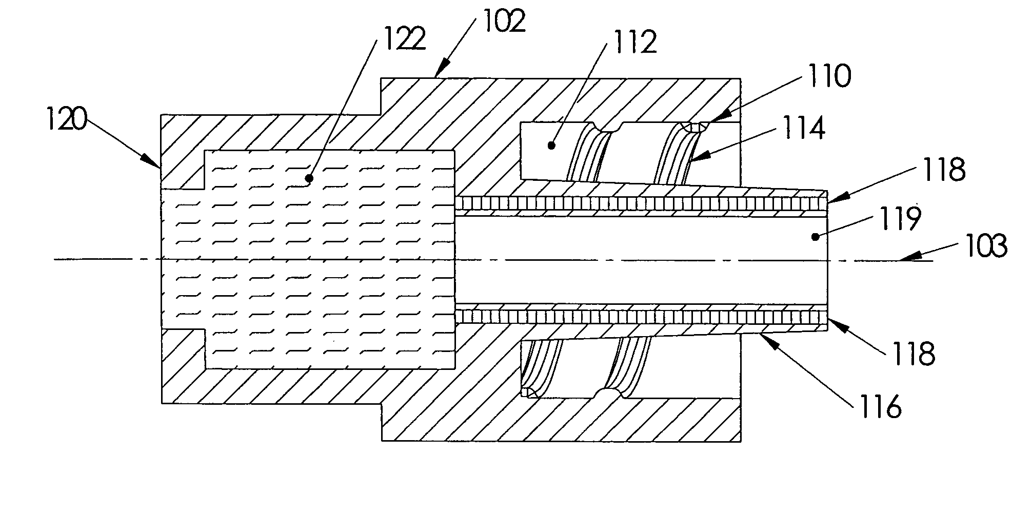
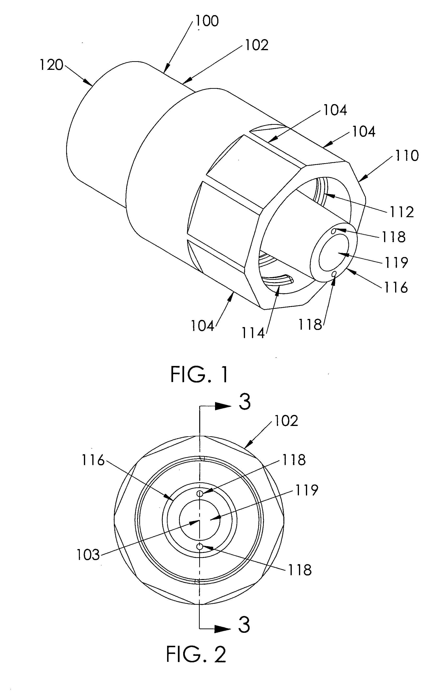
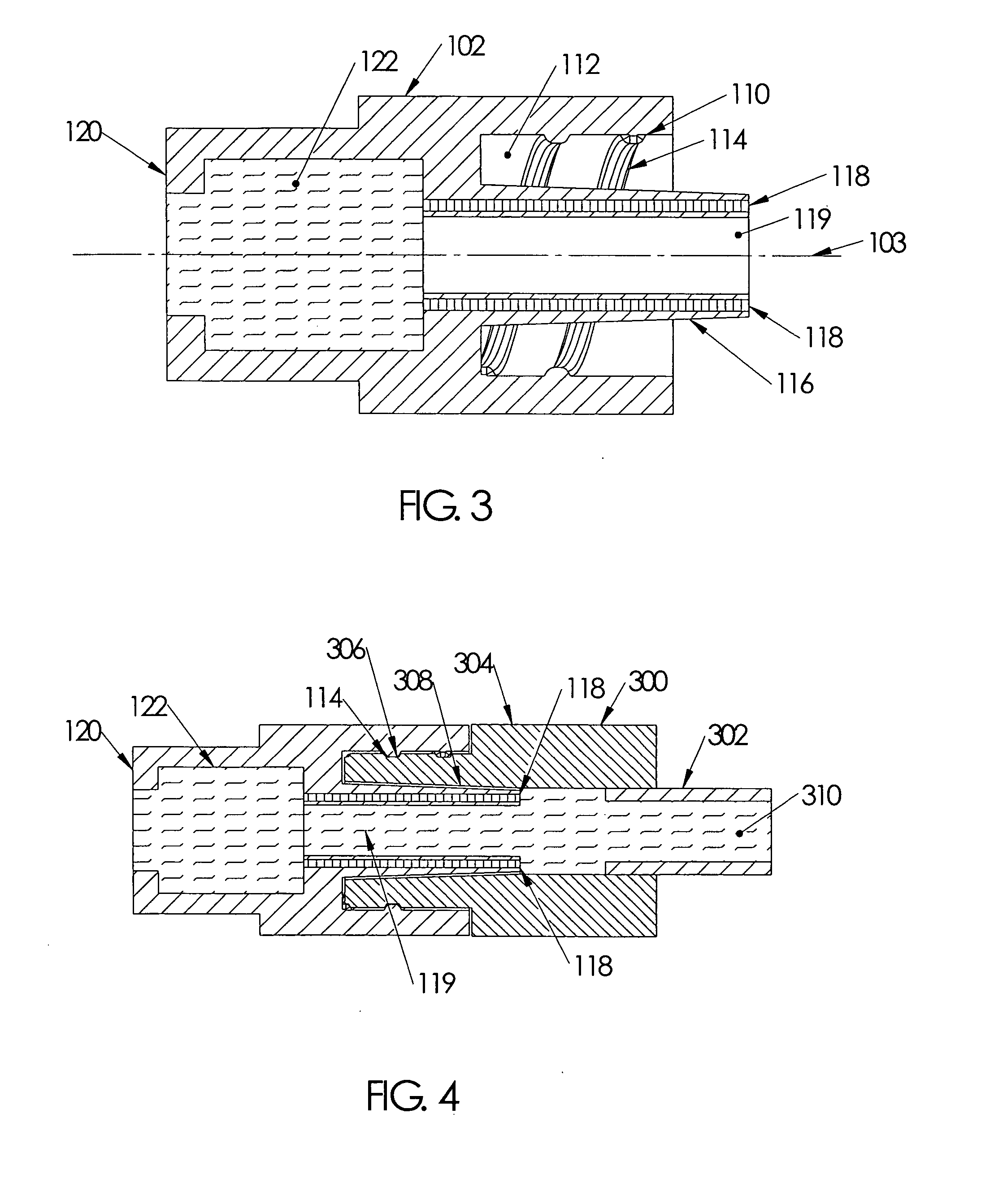
[0016] Referring to FIGS. 1-3, a luer cap 100 according to the present invention is shown. The luer fitting 100 includes a preferably generally cylindrical body 102 that includes an open first end 110 a closed second end 130, and a longitudinal axis 103 extending therethrough. The body 102 includes a plurality of flats 104 disposed about the open first end 110. The flats 104 generally provide surfaces for a user (not shown) to grip the luer fitting 100 to twist the luer fitting 100 onto or off of a female luer connection (not shown).

[0017] The first end 110 includes a generally cylindrical opening 112. The interior of the cylindrical opening 112 preferably includes a female threaded connection 114. A tapered male luer connection 116 extends through the cylindrical opening 112 along the longitudinal axis 103. The luer connection 116 includes a silver matrix 118 that is embedded in the luer connection 116, with a portion of the silver matrix 118 being in fluid communication with the e...

second embodiment

[0025] Referring now to FIG. 5, a luer cap 200 according to the present invention is shown. The luer cap 200 includes a first end 210 having a male luer connector and female threads 214, similar to the luer cap 100 described above, but with an added antibacterial component, such as a silver matrix 218, extending distally from the first end 210. The silver matrix 218 may be embedded in a stylet 220 that is fixedly connected to the luer cap 200. Preferably, the stylet 220 is generally an elongate tube with a preferably tapered distal end 222. The stylet 220 is manufactured from a polymer, such as nylon, or a thermoplastic polyurethane elastomer, such as PELLETHANE®, or some other suitable, biocompatible material. Also preferably, a passage 224 extends longitudinally through the stylet 220, with the passage fluidly communicating with a second end 230 of the luer cap 200 that is open.

[0026] The luer cap 200 also includes a threaded luer fitting 232 disposed at the second end 230 of the ...


PUM


Abstract

A luer fitting is disclosed. The luer fitting includes a body having a first end and a second end, wherein the first end comprises an antibacterial component disposed therewith. The luer fitting is connected over a catheter that has been primed with a locking solution. The antibacterial component is fluidly engaged with the locking solution such that the antibacterial component diffuses through the locking solution. A method of reducing antibacterial activity in a catheter utilizing the fitting is also disclosed.

Description

CROSS REFERENCE TO RELATED APPLICATION [0001] The present application claims the benefit of U.S. Provisional Patent Application Ser. No. 60 / 527,260, filed on 5 Dec. 2003.BACKGROUND OF THE INVENTION [0002] Catheters are used to provide repeated access to a vascular system in a patient. A catheter may be used to infuse a fluid, such as a medication or a saline solution, or withdraw a fluid, such as blood. Multiple lumen catheter assemblies, such as those used for hemodialysis, include at least one catheter for the withdrawal of blood from a blood vessel to be sent for processing in a hemodialysis machine, while another catheter returns the blood to the vessel after processing. [0003] Catheters may be inserted into a patient for acute care, where the catheter is intended to be in the patient for a short duration, such as for only a few days, or for chronic care, where the catheter is intended to be in the patient for a much longer duration, such as over several months. [0004] One of th...

Claims


Application Information

Patent Timeline
IPC IPC(8): A61M39/10A61M39/16
CPCA61M39/10A61M2039/1033A61M2025/0019A61M39/162
Inventor KUNIN, DAVIDMAENNER, JOSEPH E.
Owner MEDICAL COMPONENTS INC
Learn More