Angular velocity sensor
a technology of angular velocity sensor and angular velocity, which is applied in the direction of acceleration measurement using interia force, turn-sensitive devices, instruments, etc., can solve the problems of reducing the space requirement of the control system equipped with angular velocity sensor, and affecting the accuracy of the measurement. , to achieve the effect of reducing the whole system
- Summary
- Abstract
- Description
- Claims
- Application Information
AI Technical Summary
Benefits of technology
Problems solved by technology
Method used
Image
Examples
first embodiment
(FIRST EMBODIMENT)
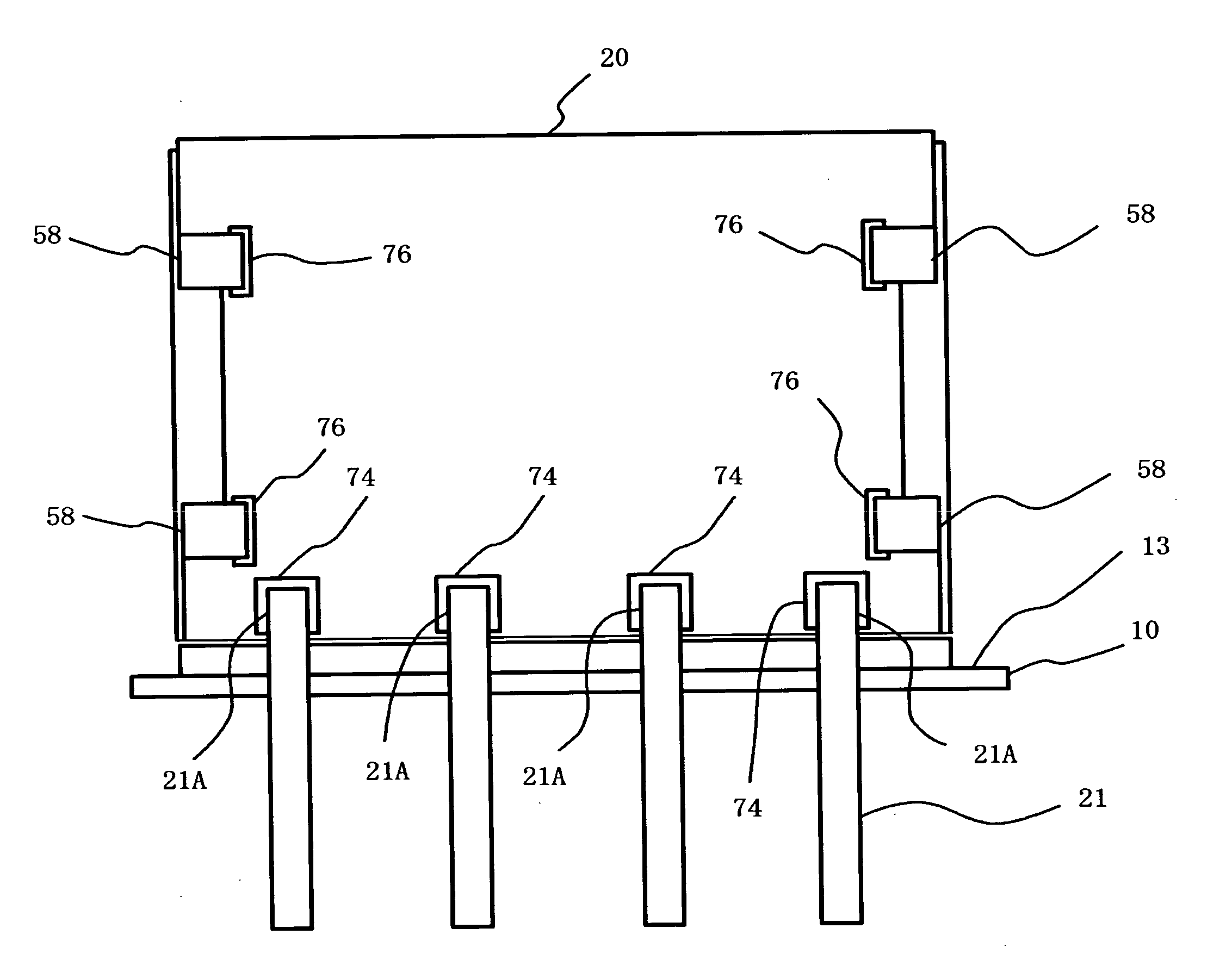
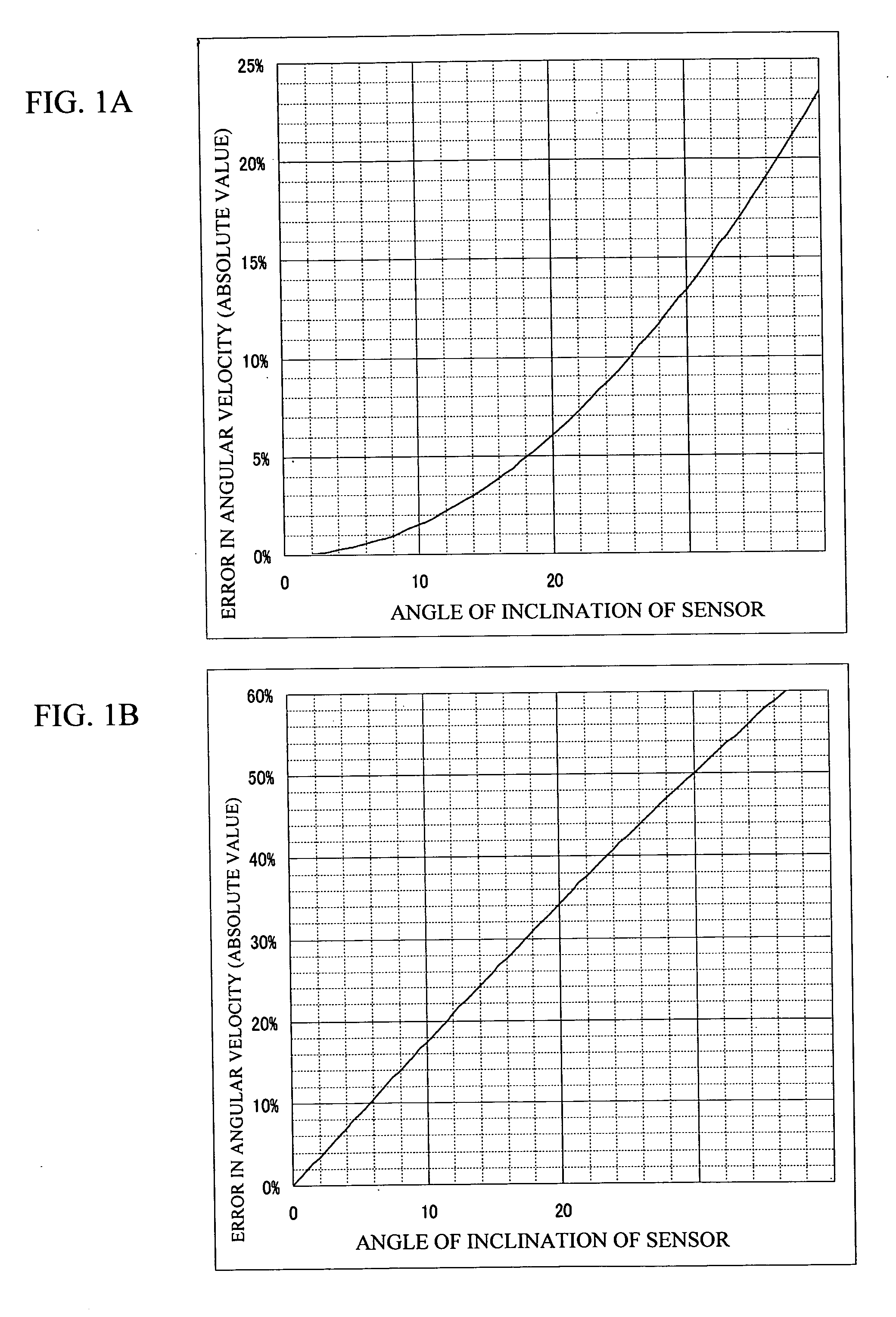
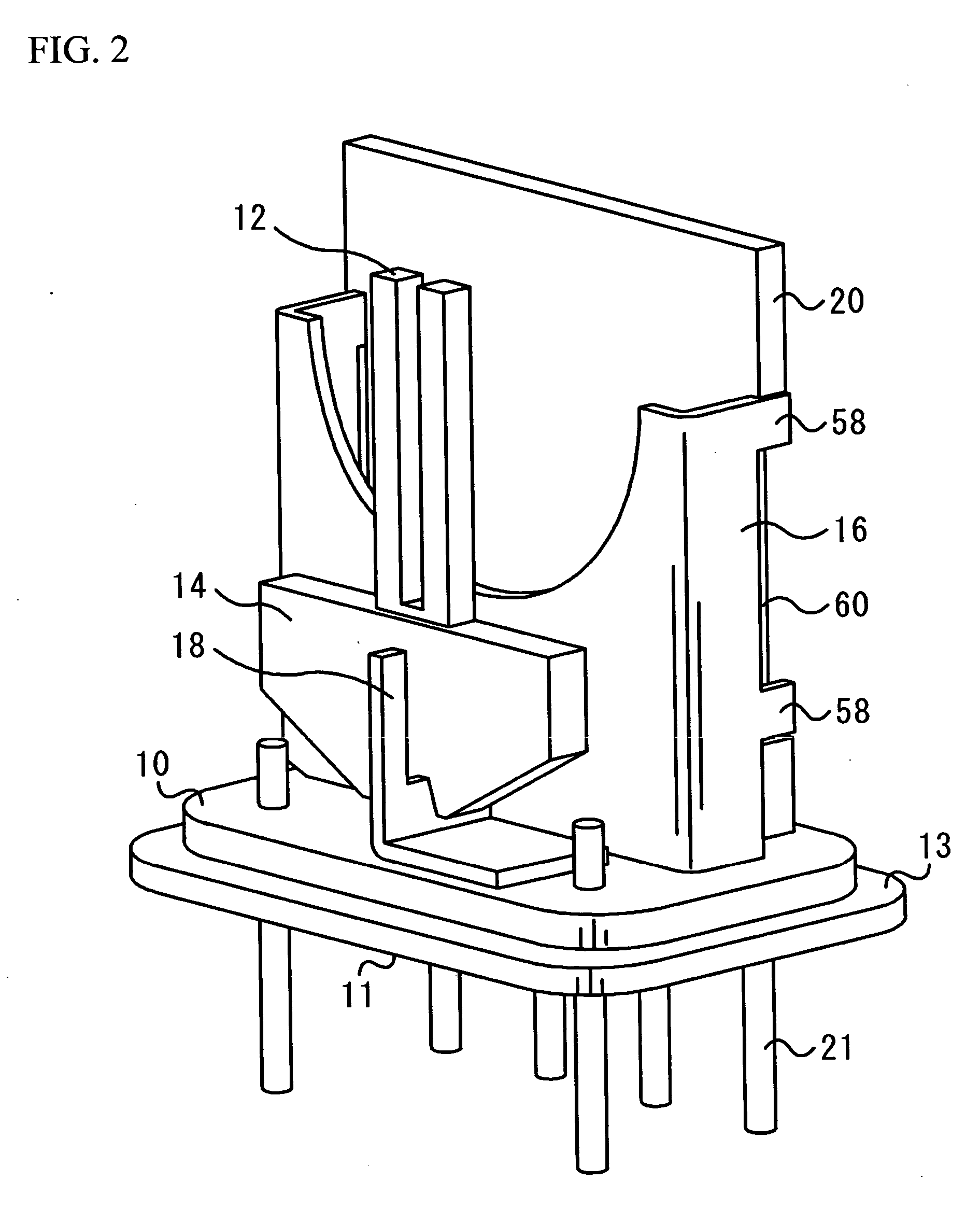
[0033] A description will be given of a first embodiment of the present invention, with reference to drawings. FIGS. 2 and 3 are perspective views of an angular velocity sensor in accordance with a first embodiment of the present invention. FIG. 2 shows a case where the angle of inclination of a vibrator is 0°. FIG. 3 shows a case where the vibrator is inclined. The angular sensor includes a stem 10, a vibrator 12, a vibrator supporting substrate 14, a frame 16, a holding member 18, a circuit board 20, and multiple external connection terminals 21. The holding member 18 is made of elastically deformable material. The angle of the vibrator 12 can be adjusted arbitrarily by elastically deforming the holding member 18, as shown in FIG. 3. The angular velocity sensor shown in FIG. 2 is suitable for the case where the stem 10 is installed on the surface that is parallel to the reference plane (the ground surface), or where the detection axis of the vibrator 12 is vertic...
second embodiment
(SECOND EMBODIMENT)
[0045]FIGS. 12A and 12B are front views of an angular velocity sensor in accordance with a second embodiment of the present invention. The second embodiment of the present invention is a variation of the first embodiment of the present invention. FIG. 12A includes the vibrator 12, the vibrator supporting substrate 14, the frame 16, the holding member 18, and the circuit board 20 of the first embodiment, which are rotated 90 degrees clockwise. FIG. 12B includes the vibrator 12, the vibrator supporting substrate 14, and the holding member 18 that are rotated 90 degrees clockwise. Referring to FIG. 12A, the holding member 18 is parallel to the mounting surface 11 of the stem 10, and the detection axis is parallel to the mounting surface 11. However, if the holding member 18 is rotated counterclockwise, the holding member 18 can be inclined to the mounting surface 11. Referring to FIG. 12B, the holding member 18 is parallel to the mounting surface 11 of the stem 10, a...
third embodiment
(THIRD EMBODIMENT)
[0047]FIG. 13 is a front view of the angular velocity sensor in accordance with a third embodiment of the present invention. A block-shape of a vibrating reed vibrator 92 is employed for the vibrator. Two holding members 98A and 98B hold around the edges of a longer side of the block-shape of the vibrating reed vibrator 92. The holding members 98A and 98B are part of the frame 96. That is, a single member is folded to shape the frame 96 and the holding members 98A and 98B. The holding member 98A is arranged on the upper side of the frame 96, and is tilted counterclockwise. The holding member 98B is arranged on the lower side of the frame 96, which is in a diagonal relationship with the holding member 98A, and is tilted counterclockwise at the same degrees as the holding member 98A. The vibrating reed vibrator 92 is held by those holding members 98A and 98B. The conventional techniques may be employed for the driving electrodes and the detecting electrodes. The abov...
PUM
 Abstract
Description
Claims
Application Information
 - Generate Ideas
- Intellectual Property
- Life Sciences
- Materials
- Tech Scout
- Unparalleled Data Quality
- Higher Quality Content
- 60% Fewer Hallucinations
Browse by: Latest US Patents, China's latest patents, Technical Efficacy Thesaurus, Application Domain, Technology Topic, Popular Technical Reports.
© 2025 PatSnap. All rights reserved.Legal|Privacy policy|Modern Slavery Act Transparency Statement|Sitemap|About US| Contact US: help@patsnap.com


