[0005] A problem with the somewhat straight-forward approach of using a one-
half rate clock with 10 PPM oscillators is that 10 PPM oscillators are very expensive as compared to the less accurate 20 PPM oscillators. Although acquisition is sufficiently robust for 20 PPM, the tracking performance can be degraded with DC offsets and
flicker noise and high-pass filter (HPF)
notching. Many low-cost receivers, such as those employing the zero
intermediate frequency (ZIF) architecture (otherwise referred to as direct conversion), contribute a significant level of DC which lies at the center of the multi-carrier received
signal. The large
frequency offset caused by the less accurate oscillators (e.g., larger PPM) appreciably shifts the receive
signal, so that DC and the HPF can potentially destroy the data-carrying subcarriers closest to zero Hz, which in turn significantly lowers performance.
[0008] The present invention describes a new approach which provides both good performance and
low complexity so that existing radios are easily modified to achieve the desired results. In various exemplary embodiments, 10 MHz
channelized OFDM is achieved with half-rate clocks and 20 PPM oscillators by
copying the information of the data subcarriers closest to zero Hz to more robust locations. In one such embodiment, the first positive-
frequency data subcarrier at frequency location or bin +1 is copied to an outermost positive-
frequency data subcarrier appended at frequency location +27 and the first negative-
frequency data subcarrier at location −1 is copied to an outermost negative-frequency data subcarrier appended at location +27, to achieve a total of 54 data subcarriers. In various exemplary embodiments, 10 MHz channelized OFDM is achieved with half-rate clocks and 20 PPM oscillators by moving the information of the data subcarriers at zero Hz to more robust locations. In one embodiment, the positive-frequency data subcarriers are shifted up and the negative-frequency data subcarriers are shifted down each by one subcarrier position. New circuitry is not required. Instead, the indexing of the
Fast Fourier transform (FFT) and
inverse FFT (IFFT) is changed to accommodate the subcarrier shift. In various exemplary embodiments, two extra Long
Sync (LS) subcarriers are added at the outer positions for a total of 54 subcarriers for the Long Syncs. The additional LS subcarriers appear to the LS correlator as an insignificant amount of
noise so that the existing LS correlation and detection circuitry need not be modified. The additional pair of subcarriers enables retention of the periodicity property of the Long Syncs. In the
receiver for LS FEQ
estimation, the additional LS subcarriers are separately read and the FEQ is separately calculated, and the innermost subcarriers are discarded.
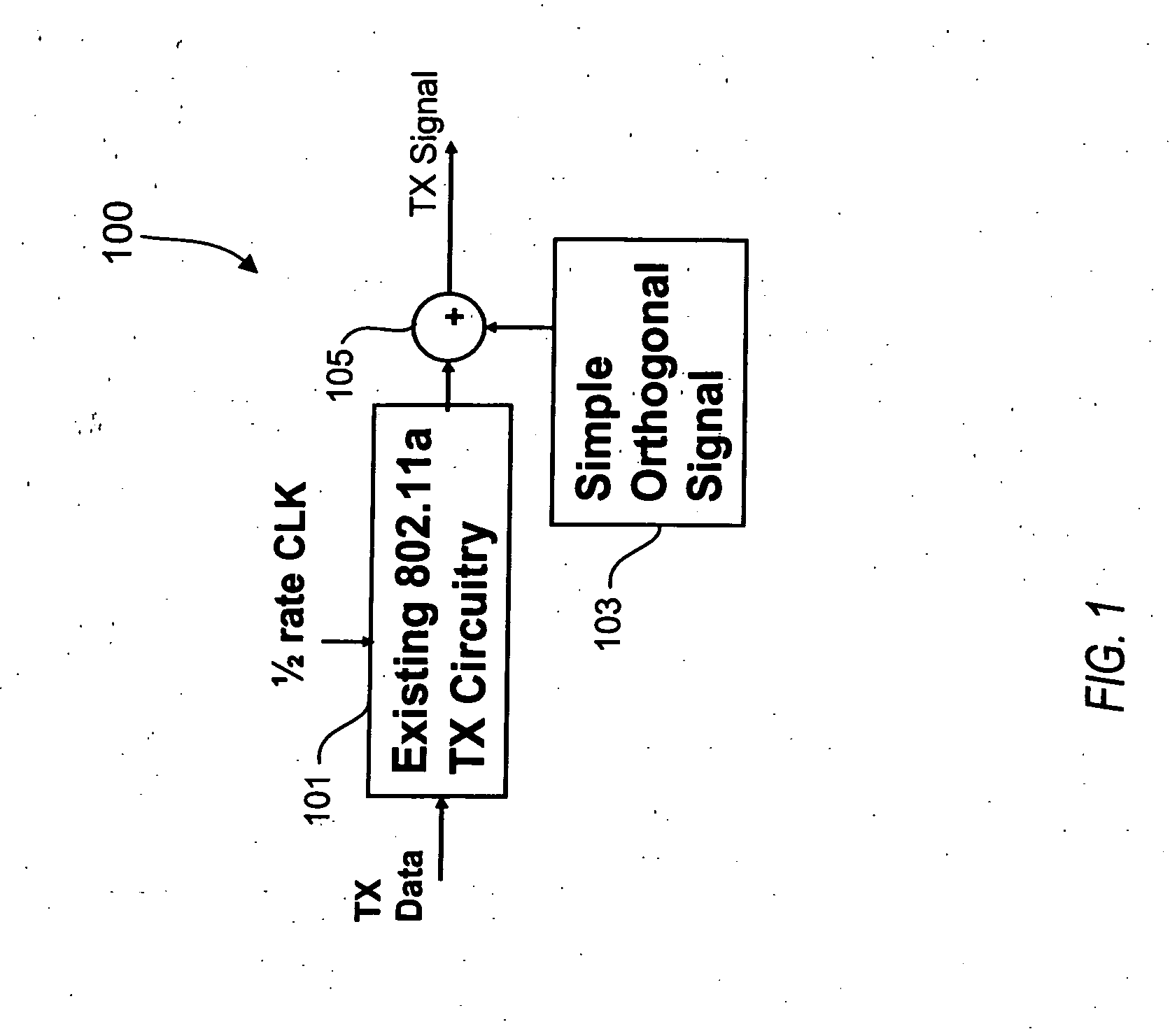
[0009] Alternative configurations are illustrated for both the
transmitter and
receiver. In one embodiment of the transmitter, the existing transmitter circuit is operated at half-rate using a 20 PPM oscillator and slightly modified to copy the complex coefficients associated with the data subcarriers at the innermost frequency locations and apply the duplicate coefficients to the appended outermost data subcarriers in the
frequency domain prior to Inverse
Fast Fourier Transform (IFFT)
processing. In an alternative transmitter embodiment, the existing transmitter circuitry is unmodified and new circuitry is added in parallel to duplicate the complex coefficients at the innermost bin locations and apply them to
time domain samples of tones associated with the outmost redundant subcarriers, and add the results in the
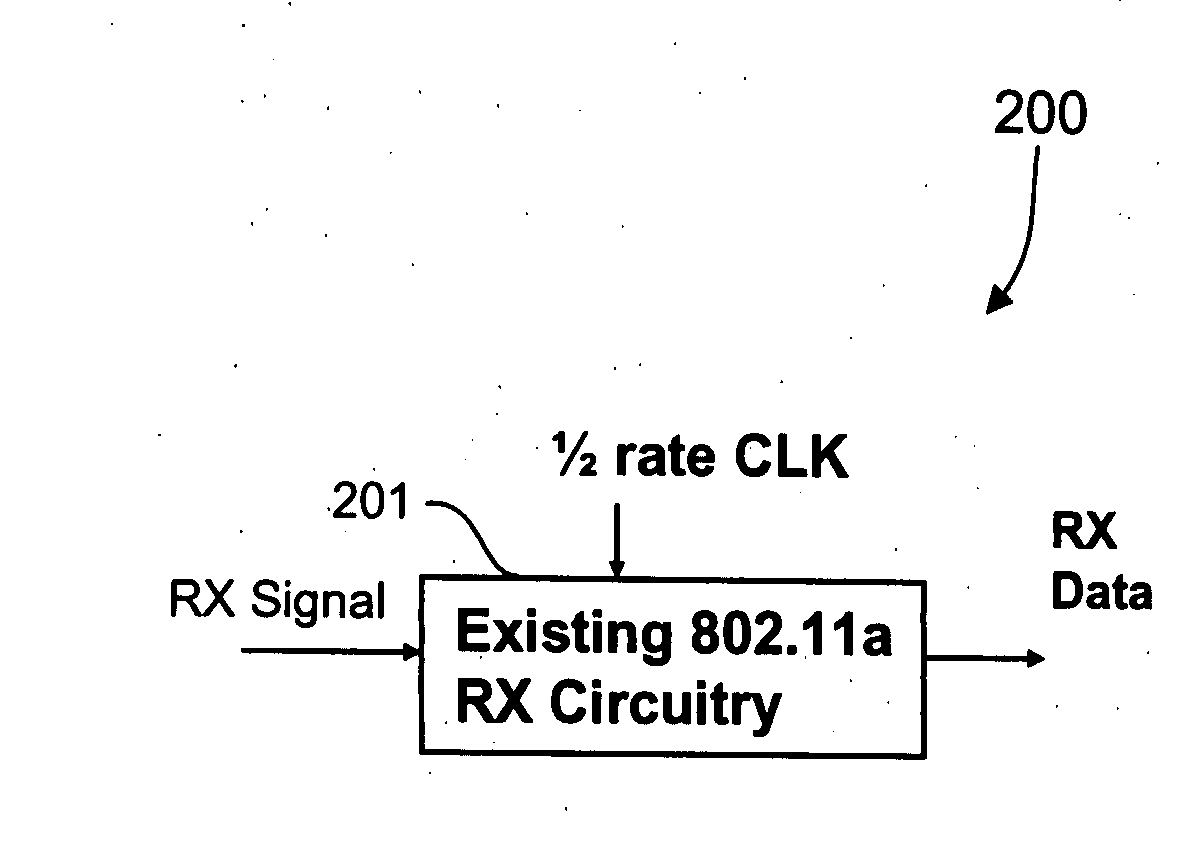
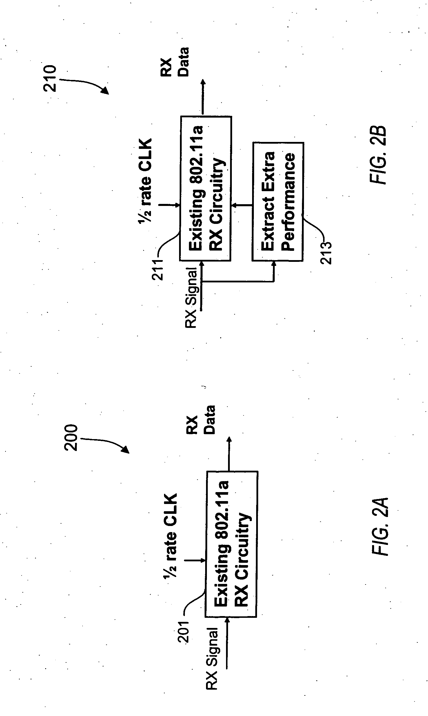
time domain. In one embodiment, the existing
receiver circuit is used as-is at half-rate. In this first case, the additional subcarriers appear as a relatively minimal amount of extra
noise and are ignored. In an alternative embodiment, the receive circuitry is slightly modified to read the appended redundant subcarriers. In this second case, several alternatives are possible. In one embodiment, the receiver simply ignores the potentially corrupted inner-most data subcarriers and always uses the appended redundant subcarriers. Alternatively, the receiver selects between the inner-most and outermost subcarriers and selects the best subcarriers. Alternatively, the receiver coherently combines the extra subcarriers, such as using an optimal weighting function or the like. In another alternative embodiment, the
pilot tones are not shifted and the remaining data subcarriers are shifted outwards and around the stationary pilot tones. In yet another alternative embodiment, the inner-most data subcarriers are duplicated and appended to the subcarrier profile on either side of the outer subcarrier positions. For any of the embodiments described herein, only very minimal changes are necessary to existing radio designs. This further enables multi-mode radios, e.g., radios that support 802.11a / g / j and DSRC.
