
Implantable medical system with long range telemetry

a technology of medical devices and telemetry, applied in the field of medical devices, can solve the problems of consuming significant power, unidirectional nature of biotronik long range data communication system, and cc1000 chipset from chipcom

Inactive Publication Date: 2005-05-26
ANGEL MEDICAL SYST +1
View PDF83 Cites 296 Cited by
  • Summary
  • Abstract
  • Description
  • Claims
  • Application Information

AI Technical Summary

Benefits of technology

[0010] An additional object of the present invention is to provide an implantable medical device with long range telemetry where an antenna may be located outside of the device casing and provided with its own feed through the casing.
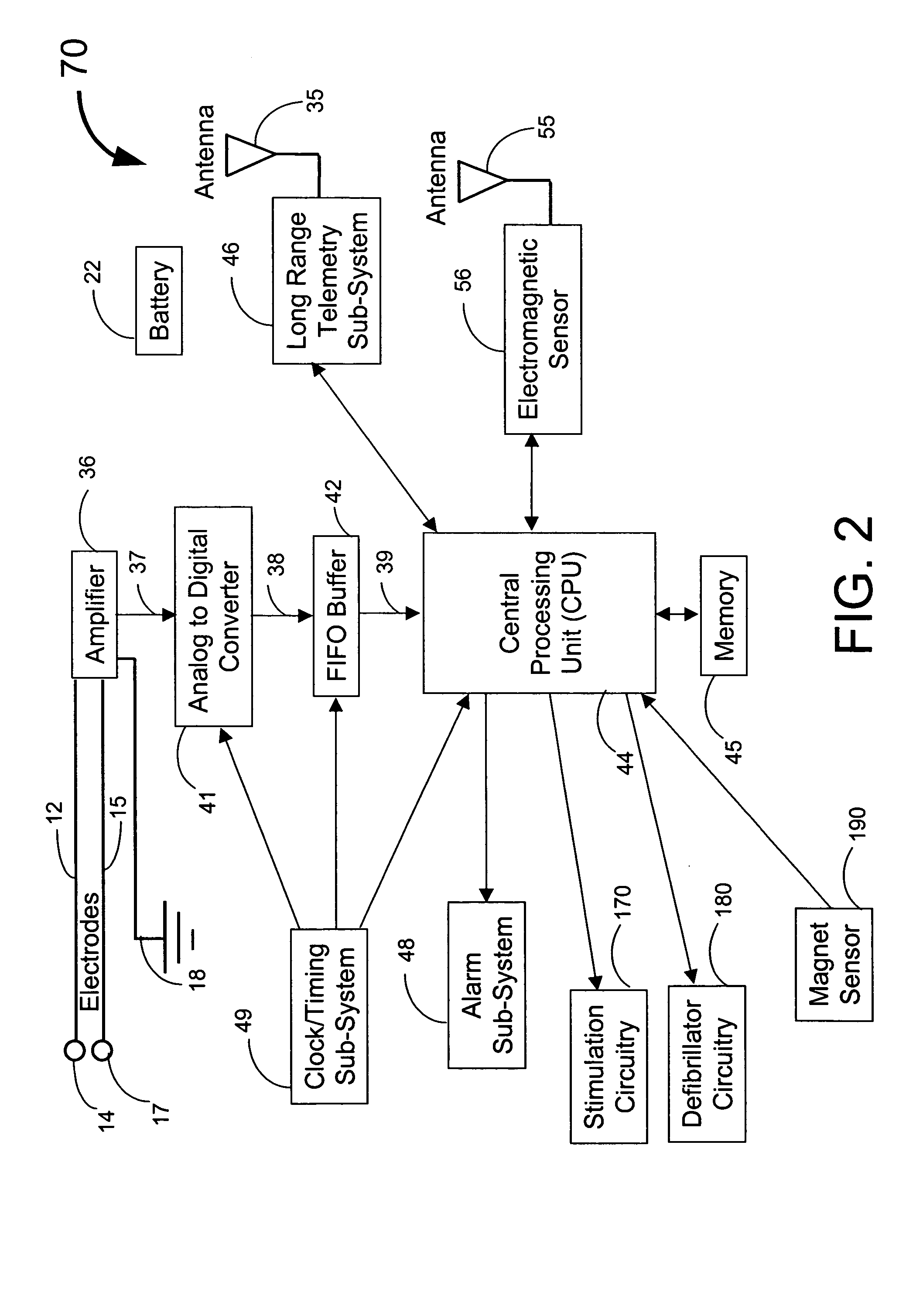
[0024] The high power burst technique sends an electromagnetic signal burst from a device located six inches or more away from the implant. The signal has sufficient intensity when received by the near field receiver circuitry in the implant to activate the long range telemetry system, much as with the near field activation technique. Specific security codes may be included in the near field activation signal or high power burst signal to minimize or eliminate the chance of inadvertently activating the long range telemetry circuitry for other signal sources.

Problems solved by technology

However, the Biotronik long range data communication system is unidirectional, meaning that data are transmitted in one direction, e.g., only from the implant to the remote receiver.
Such telemetry sub-systems, for example, the CC1000 chipset from CHIPCOM, consume significant power during the “listening” phase of their operation.
This precludes fast time response of the implanted devices to commands from the remote equipment.
None of the above arrangements is ideal, for the placement of a telemetry antenna in the header or a plastic outer casing of the implant limits the usable antenna length, while employing a lead of the implant as the antenna causes RF energy to be delivered into the heart.
Using a second conductor in the lead as the antenna is not desirable as it also has the negative effect associated with delivering RF energy into the heart.

Method used


Image

  • Implantable medical system with long range telemetry
  • Implantable medical system with long range telemetry
  • Implantable medical system with long range telemetry

Examples


Embodiment Construction

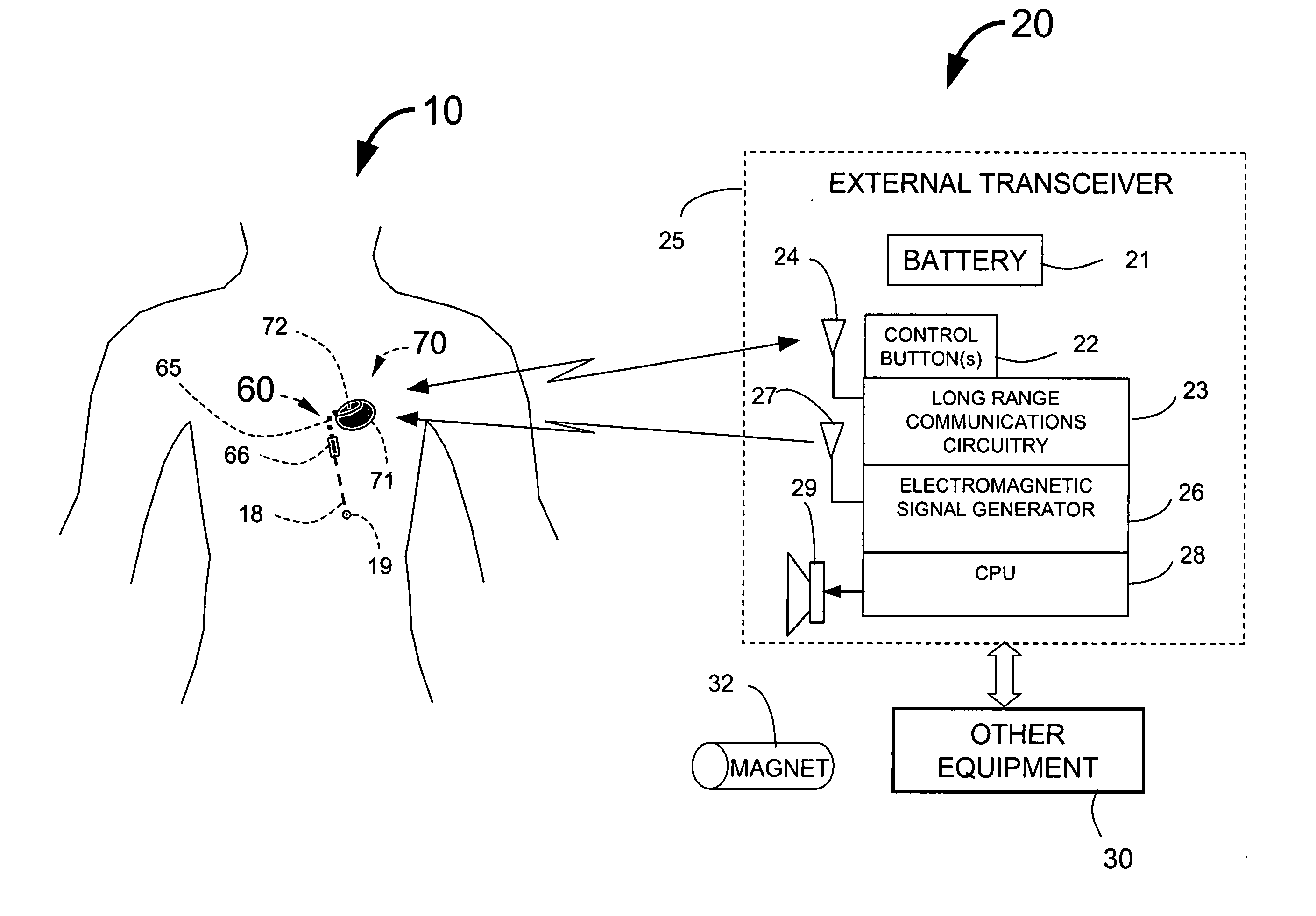
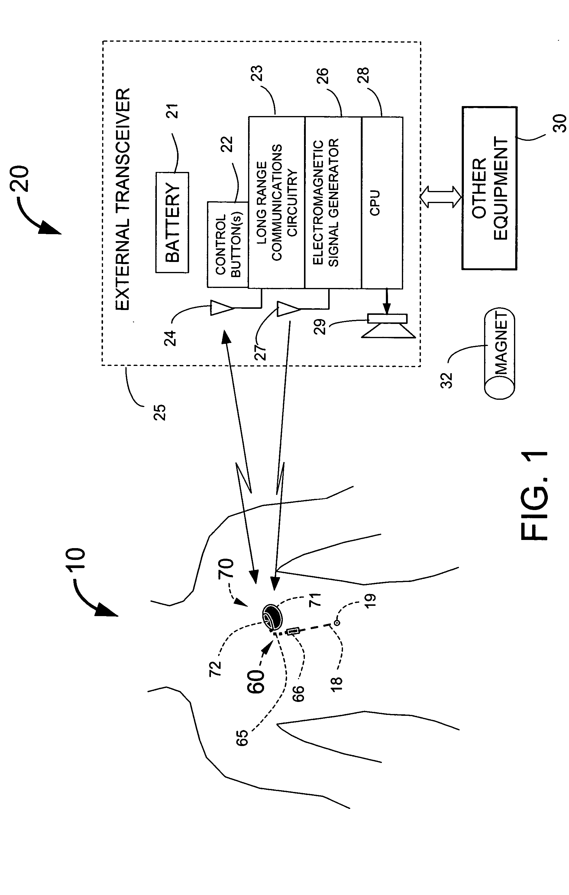
[0044] Regarding FIG. 1, an implantable medical system with long range telemetry of the present invention includes an implanted portion 10 and an external portion 20. The implanted portion 10 includes an implanted medical device (also referred to herein as an implant) 70 having a connecting cable 60 with a lead connector 66 that attaches to a lead 18 having electrode(s) 19. The implant 70 includes a casing 71 and a header 72. The implant 70 may be a diagnostic device with patient alerting capability such as described by Fischell, et al. in U.S. Pat. No. 6,609,023, or it may be a therapeutic device such as a pacemaker, Implantable Cardiac Defibrillator (ICD), an implantable drug pump, or the like.

[0045] The external portion 20 includes an external transceiver 25. A battery 21 may be embedded into the external transceiver 25 which is connected to other equipment 30. The other equipment 30 may include a physician's programmer and other display and command devices such as PDAs or cell ...


PUM


Abstract

An implantable medical system for implantation within the body of a patient is provided. The system includes an implanted device having an implant casing and a long range telemetry sub-system housed therein. The system also includes an implantable lead operationally coupled to the implanted device and an antenna coupled to the implant casing to extend therefrom. The antenna is operationally coupled to the long-range telemetry sub-system to enable wireless bi-directional communication between the long range telemetry sub-system and predetermined external equipment disposed outside the body of the patient.

Description

[0001] This Utility patent Application is based on the Provisional patent Application No. 60 / 524,077 filed 24 Nov. 2003.FIELD OF THE INVENTION [0002] This invention relates to the field of medical devices implantable within a human patient and having the ability to communicate with remote equipment. BACKGROUND OF THE INVENTION [0003] Known implantable devices including pacemakers and Implantable Cardiac Defibrillators (ICDs) include the capability to communicate with remote equipment while implanted in the body of a patient. Such communication occurs by means of an antenna of the remote equipment placed within inches of the implant to be able to reliably send and receive data to / from that implant. Recently, Biotronik Company has developed a long range telemetry system for pacemakers that allows data from the pacemakers to be transmitted to a remote receiver disposed several meters away from the patient. However, the Biotronik long range data communication system is unidirectional, m...

Claims


Application Information

Patent Timeline
Patent Type & Authority Applications(United States)
IPC IPC(8): A61N1/05A61N1/372
CPCA61N1/056A61N1/37252A61N1/37229
Inventor FISCHELL, DAVID R.TURI, GREGGJOHNSON, STEVEN R.
Owner ANGEL MEDICAL SYST
Learn More