
Method and circuit for sensing the transition density of a signal and variable gain phase detecting method and device

a phase detection and transition density technology, applied in the field of linear phase detectors, can solve the problems of increasing the probability of erroneous recognition of received bits, data receivers may receive significantly distorted signals, and the frequency of the recovered clock is no longer adjustable by the pll loop, so as to improve the performance of the phase-locked loop (pll) loop

Inactive Publication Date: 2005-05-26
STMICROELECTRONICS SRL
View PDF6 Cites 5 Cited by
  • Summary
  • Abstract
  • Description
  • Claims
  • Application Information

AI Technical Summary

Benefits of technology

[0017] In view of the foregoing background, an object of the invention is to improve the performance of a phase-locked loop (PLL) loop.

Problems solved by technology

In long distance transmission systems operating at high bit rates over standard signal fiber lines, data receivers may receive significantly distorted signals.
Inter-symbolic interference, finite bandwidth, fiber nonlinearity and other non-idealities increase the probability of erroneous recognition of a received bit.
During these intervals the PLL loop is no longer able to adjust the frequency of the recovered clock.
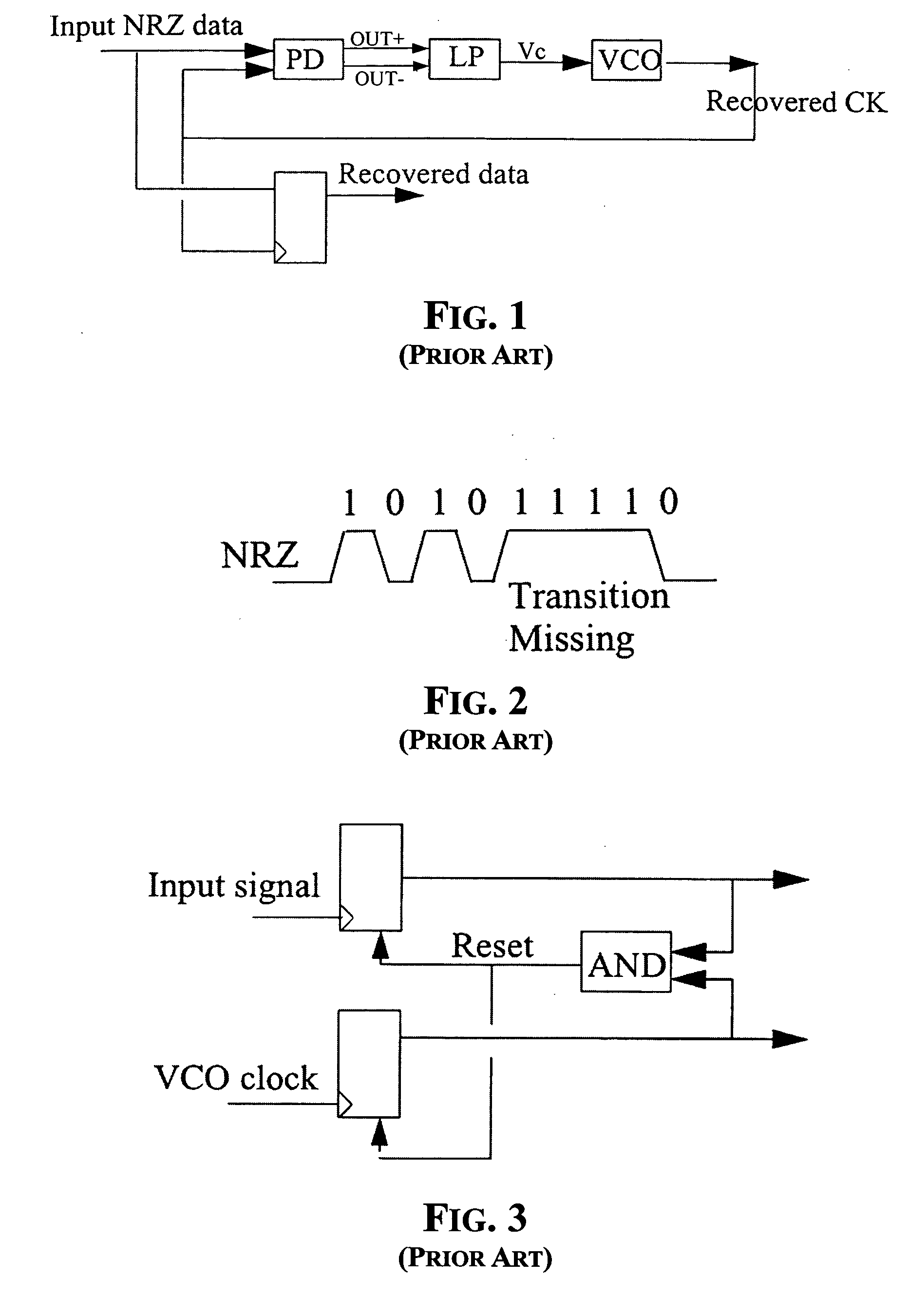
A disadvantage of this architecture is that it does not work when there is an absence of transitions in the input signal, and so it is not usable for regenerating data for a NRZ transmission system.
The disadvantage of this phase detector is that its output is not proportional to the phase error between data and the clock, i.e., this phase detector has a non-linear transfer function.
This increases the frequency jitter of the recovered clock.
Unfortunately, it is very difficult to use them when the data rate is relatively high because they are based on the use of flip-flops, which require a certain time for generating a stable output.
If the phase detector PD is to function at significantly different bit rates and / or with NRZ signals, it becomes difficult to optimize the gain at the design stage if the contemplated operating frequencies vary within a broad range.

Method used


Image

  • Method and circuit for sensing the transition density of a signal and variable gain phase detecting method and device
  • Method and circuit for sensing the transition density of a signal and variable gain phase detecting method and device
  • Method and circuit for sensing the transition density of a signal and variable gain phase detecting method and device

Examples


Embodiment Construction

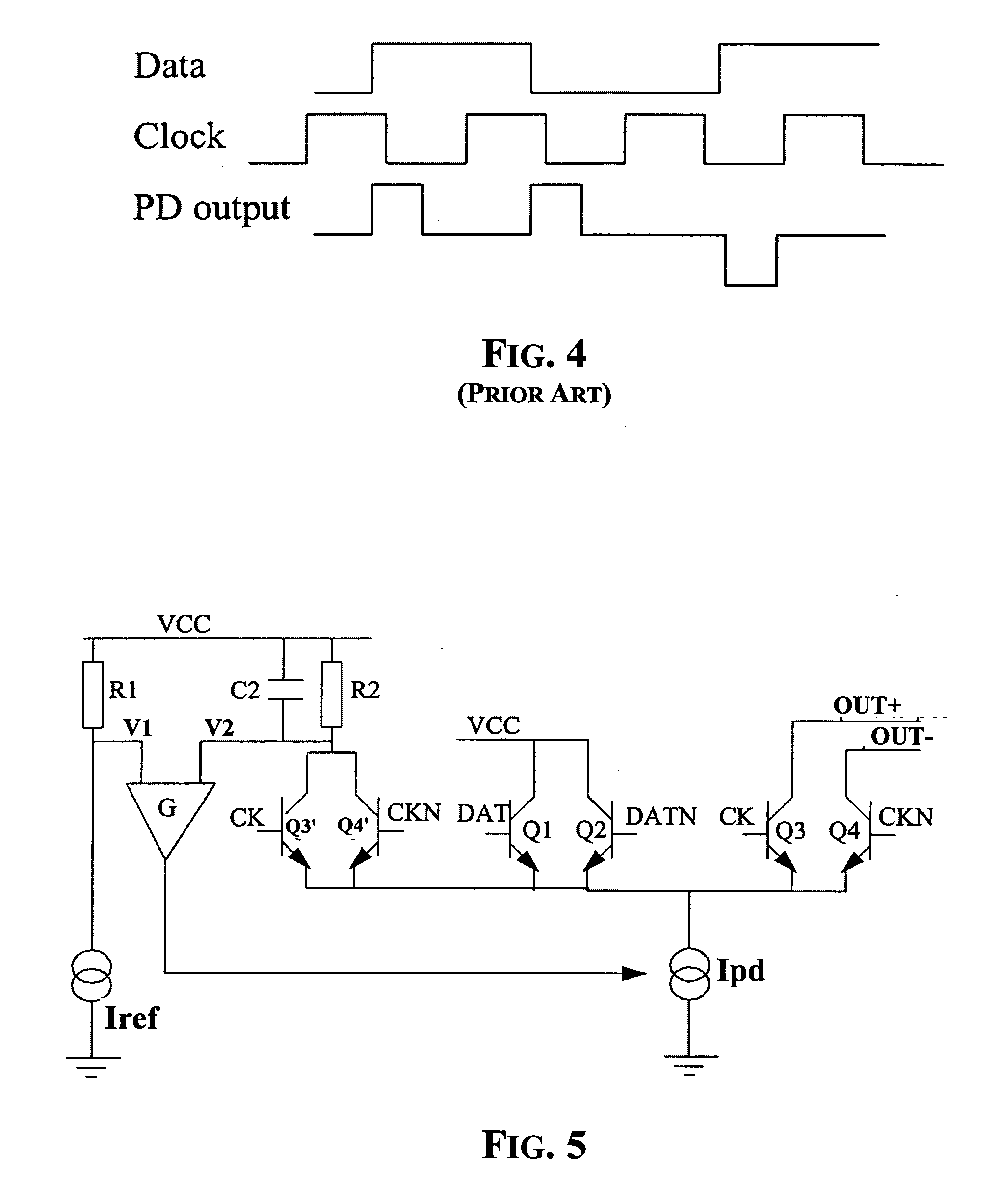
[0027] A sample embodiment of a variable gain linear phase detector of the invention is depicted in FIG. 5. The phase detector is composed of a first differential pair of transistors Q3, Q4 controlled by the clock CK and by its inverted replica CKN for outputting the differential current signal OUT+, OUT−, and a second differential pair of transistors Q1, Q2 controlled by the digital input signal DAT and by its inverted replica DATN. The two differential pairs of transistors Q1, Q2 and Q3, Q4 are biased by a common current generator Ipd. The current from the common current generator Ipd is regulated by a feedback loop to vary the gain of the differential output stage Q3, Q4, according to the invention.

[0028] The regulation loop is implemented by adding a third differential pair of transistors Q3′, Q4′ that may be identical or scaled replicas of the transistors Q3, Q4 of the first (output) differential pair. The third differential pair of transistors Q3′, Q4′ are similarly driven by...


PUM


Abstract

A linear phase detector has a variable gain that is regulated as a function of the monitored transition density of the input signal. The transition density is sensed by a circuit that generates a signal corresponding to a time averaged common mode component of the differential signal output by an output stage of the phase detector.

Description

FIELD OF THE INVENTION [0001] The present invention relates in general to linear phase detectors generating a differential signal representing a phase difference between two input signals. BACKGROUND OF THE INVENTION [0002] In long distance transmission systems operating at high bit rates over standard signal fiber lines, data receivers may receive significantly distorted signals. Inter-symbolic interference, finite bandwidth, fiber nonlinearity and other non-idealities increase the probability of erroneous recognition of a received bit. For these reasons, it is often necessary to place, along the transmission line, data regenerating channel systems that sample a received signal and retransmit it to either a successive data regenerating system or to the end receiver. [0003] The incoming data at the receiver may be considered as a varying analog signal from which a synchronization or clock signal may be recovered. Recovering the clock in the form of a signal that generally oscillates...

Claims


Application Information

Patent Timeline
IPC IPC(8): H03D13/00H03L7/085H04L7/033
CPCH03D13/00H04L7/033H03L7/085
Inventor CENTURELLI, FRANCESCOPOZZONI, MASSIMOSCOTTI, GIUSEPPETRIFILETTI, ALESSANDRO
Owner STMICROELECTRONICS SRL
Learn More