
Method and apparatus for polishing a substrate while washing a polishing pad of the apparatus with at least one free-flowing vertical stream of liquid

a technology of polishing pad and washing liquid, which is applied in the direction of lapping machines, manufacturing tools, and abrasive surface conditioning devices, etc., can solve the problems of constant source of defects, difficult to clean the slurry, and damage to the substrate, so as to prevent the rebounding of the washing liquid, prevent the rebounding of the slurry, and eliminate the polishing-pollutant from the polishing pad

Inactive Publication Date: 2005-05-19
JAE MAN HO +1
View PDF18 Cites 4 Cited by
  • Summary
  • Abstract
  • Description
  • Claims
  • Application Information

AI Technical Summary

Benefits of technology

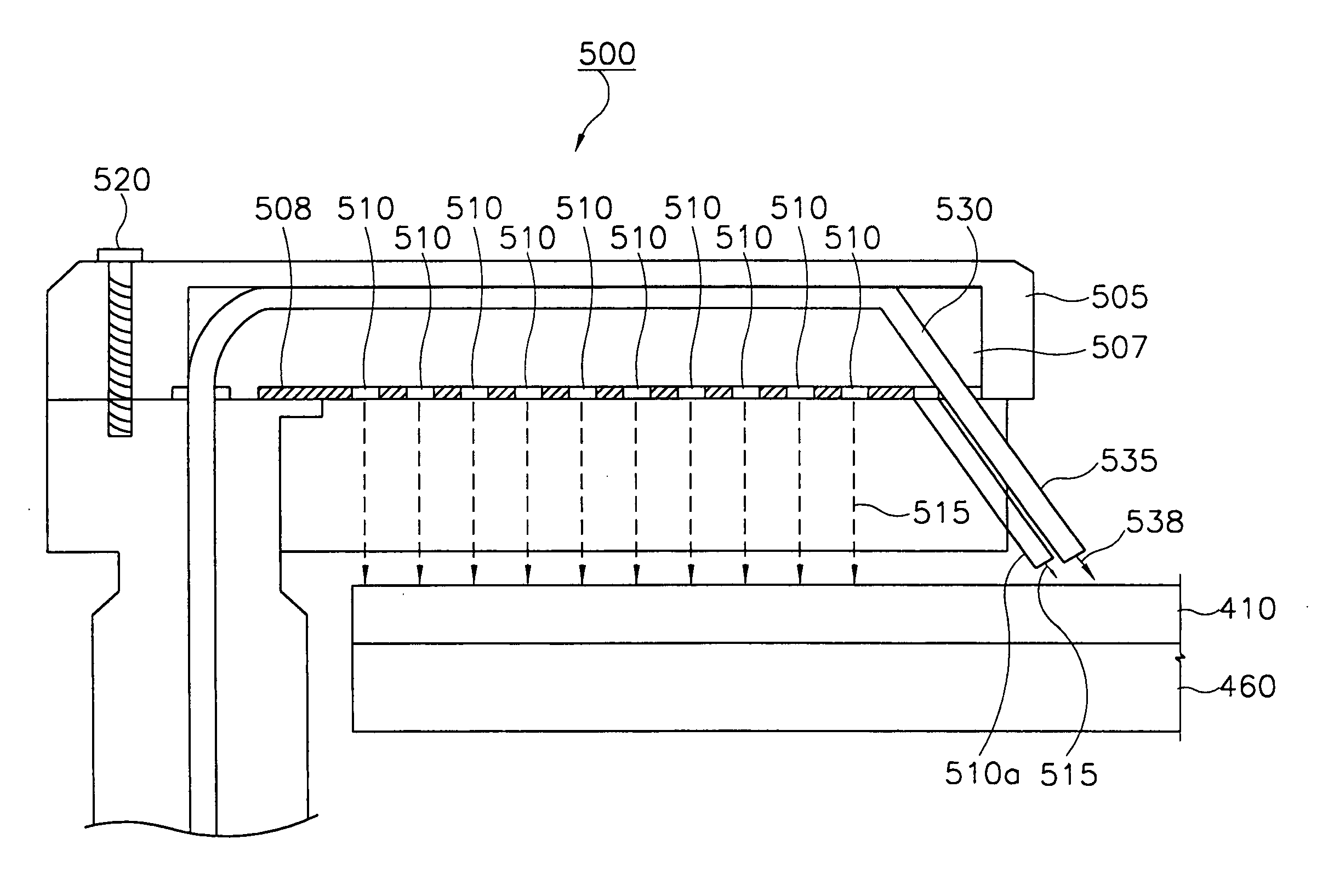
[0013] The present invention has been developed in view of the above-mentioned problems of the prior art. Accordingly it is a first object of present invention to provide a method of polishing a substrate which can minimize the rebounding of washing liquid from the polishing pad. Likewise, it is a second object of the present invention to provide an apparatus for polishing a substrate which can dispense a washing solution onto a polishing pad during the polishing operation in such a way as to minimize the rebounding of the washing liquid from the polishing pad.
[0014] To achieve the first object of the present invention, the method of polishing a substrate comprises steps of rotating a substrate, rotating a polishing pad, polishing a surface of the substrate by placing the substrate in contact with the polishing pad and supplying slurry onto the polishing pad, and eliminating polishing-pollutants produced as a result of the polishing of the substrate by directing washing solution onto the polishing pad in the form of at least one free-flowing vertical stream to prevent the washing liquid from rebounding from the polishing pad.
[0016] To achieve the second object of the present invention, the polishing apparatus comprises a polishing station, a polishing pad mounted to the polishing station for contacting a substrate to polish the substrate, and a washing device located at one side of the polishing pad and having at least one feed hole through washing liquid flows freely onto the polishing pad as a vertically stream to eliminate polishing-pollutants from the polishing pad.
[0017] According to the present invention, because the washing liquid flows vertically and freely onto the polishing pad, the washing liquid is prevented from rebounding. Therefore, the splashing of the slurry due to the rebounding of the washing liquid is also be minimized. As a result, slurry is prevented from accumulating on components of the polishing apparatus including on the washing device. Hence, defects in the polishing process, which are otherwise caused by agglomerations of slurry falling off of components of the polishing apparatus and onto the polishing pad during the polishing operation, are prevented.

Problems solved by technology

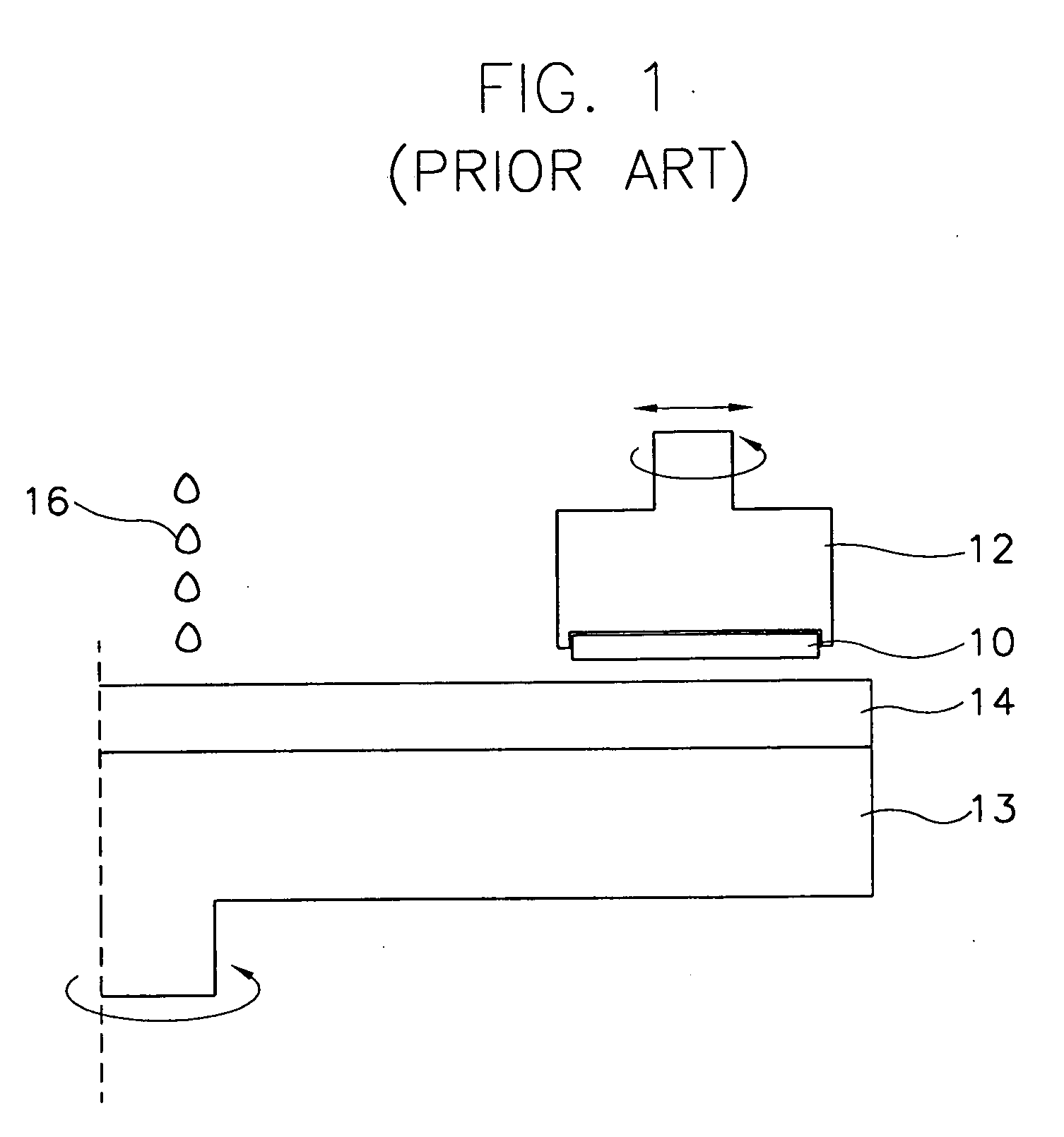
If these particles and slurry were to remain on the polishing pad, they could cause a defect to occur on a substrate as it is being polished.
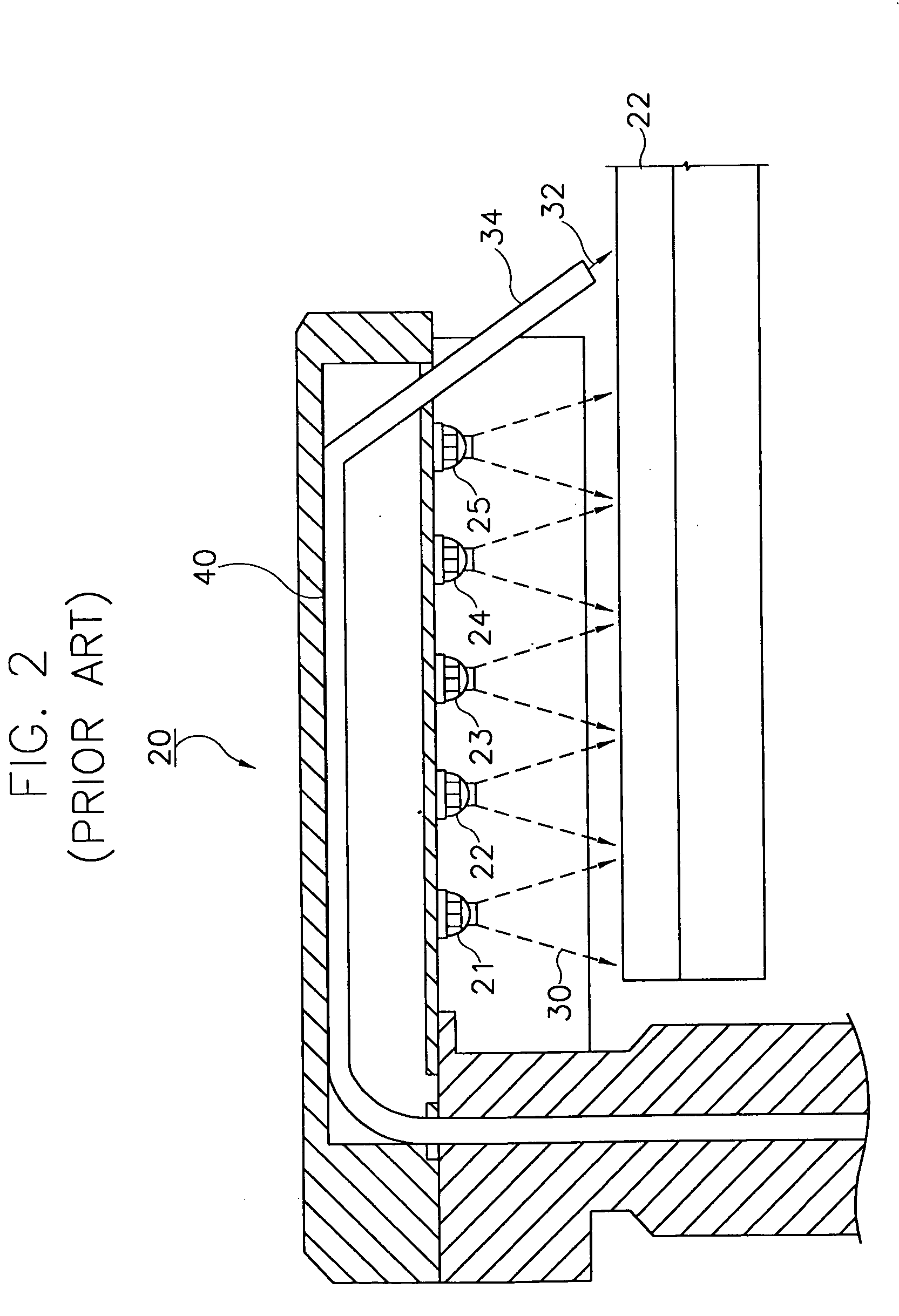
That is, it is difficult to clean the slurry, especially from the components of the polishing apparatus.
In a short, the slurry entrained by the deionized water rebounding from the polishing pad is a constant source of defects during the polishing process.
These defects, which occur on the substrates, decrease the reliability of the semiconductor devices manufactured therefrom.

Method used


Image

  • Method and apparatus for polishing a substrate while washing a polishing pad of the apparatus with at least one free-flowing vertical stream of liquid
  • Method and apparatus for polishing a substrate while washing a polishing pad of the apparatus with at least one free-flowing vertical stream of liquid
  • Method and apparatus for polishing a substrate while washing a polishing pad of the apparatus with at least one free-flowing vertical stream of liquid

Examples


Embodiment Construction

[0028] Hereinafter, preferred embodiments of the present invention will be described in detail with reference to the attached drawings.

[0029] Referring to FIG. 4, an apparatus 40 for polishing a substrate includes a polishing station 400 at which a plurality of polishing pads 410 are disposed, and a carrier supporting a plurality of carrier heads 420. Each carrier head 420 presses a substrate 430 against a polishing pad 410 whereupon a surface of the substrate 430 is polished.

[0030] More specifically, referring to FIG. 5, the polishing pad 410 is mounted on platen 460 connected to a rotary member 450. The rotary member 450 comprises a motor for rotating the polishing pad 410. That is, the polishing pad 410 is rotated while the surface of the substrate 430 is polished.

[0031] The carrier head 420 includes a vacuum chuck that grasps the substrate 430 by creating a vacuum at a side of the substrate opposite that which is to be polished. While the substrate 430 is so grasped, the carr...


PUM

PropertyMeasurementUnit
heightaaaaaaaaaa
diameteraaaaaaaaaa
timeaaaaaaaaaa

Abstract

A method and apparatus for polishing a substrate with a polishing pad and slurry entails washing polishing-pollutants produced by the polishing operation off of the pad in such a way that the pollutants are not splashed onto components of the polishing apparatus. A washing solution for removing the pollutants is directed onto the polishing pad as at least one free-flowing vertical stream. because the washing solution flows freely and vertically as it impinges the polishing pad, the washing solution does not rebound from the pad and flows from the surface of the polishing pad without causing the pollutants on the pad to be splashed up from the surface of the pad.

Description

BACKGROUND OF THE INVENTION [0001] 1. Field of the Invention [0002] The present invention relates to a method and an apparatus for polishing a substrate using a polishing pad and slurry. More particularly, the present invention relates to the washing of the polishing pad to remove slurry and other particles therefrom. [0003] 2. Description of the Related Art [0004] Recently, the semiconductor industry has made great strides as the use of information media including computers has increased. As concerns its function, a semiconductor device must operate at a high speed and have a large data storage capacity. Accordingly, improvements in semiconductor manufacturing techniques have centered around increasing the degree of integration, reliance and response speed of semiconductor devices. [0005] Chemical mechanical polishing (CMP) was developed in the 1980s for increasing the degree of integration of semiconductor devices. CMP is a manufacturing technique for polishing a surface on a subs...

Claims


Application Information

Patent Timeline
Patent Type & Authority Applications(United States)
IPC IPC(8): B24B53/007B24B1/00B24B37/00C23F1/00H01L21/302H01L21/304H01L21/306H01L21/461
CPCB24B53/017H01L21/304
Inventor JAE, MAN-HOKIM, MIN-GYU
Owner JAE MAN HO
Learn More