Vacuum pump provided with vibration damper
- Summary
- Abstract
- Description
- Claims
- Application Information
AI Technical Summary
Benefits of technology
Problems solved by technology
Method used
Image

Examples
first embodiment
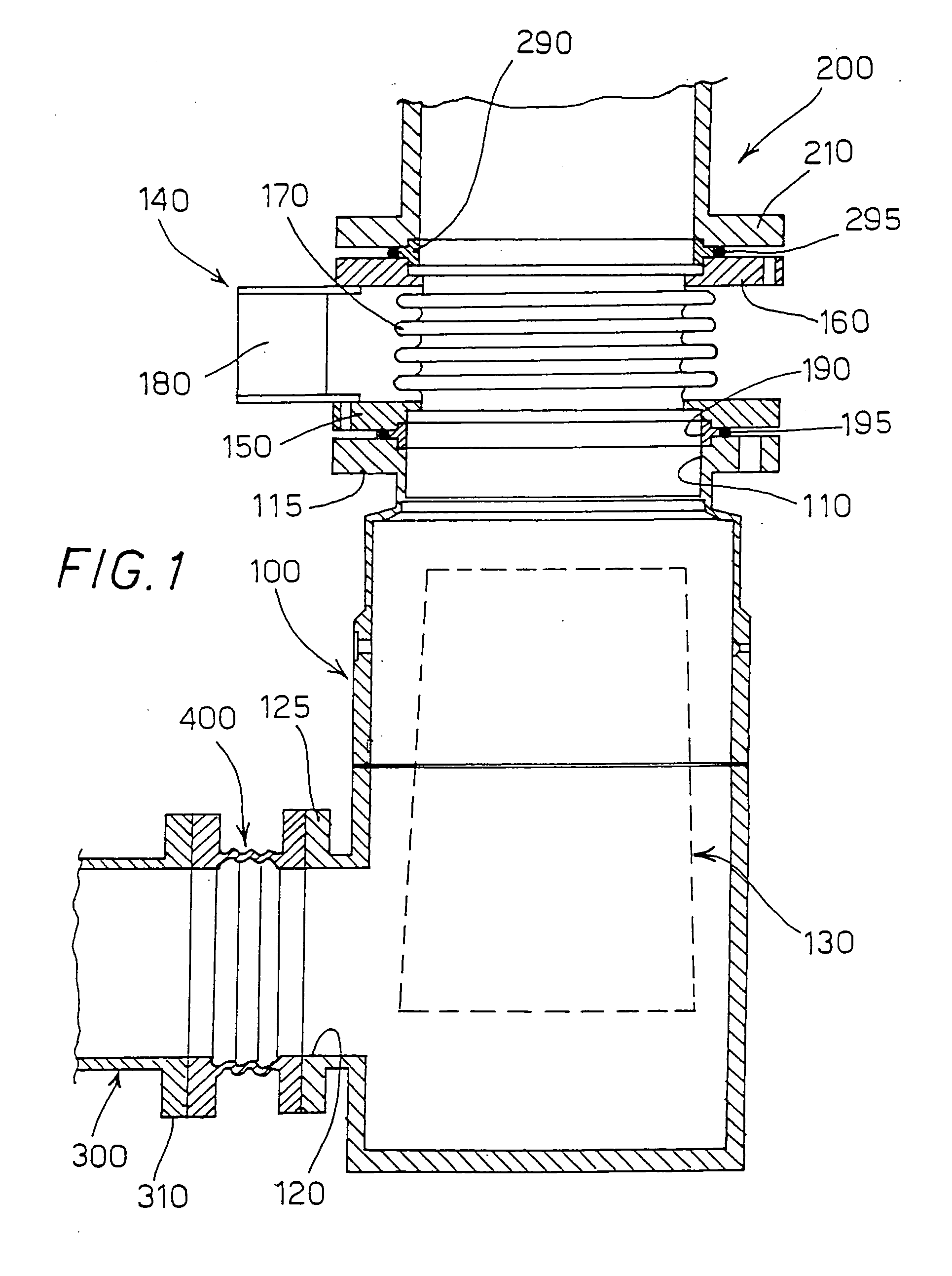
[0039] Referring to FIG. 3a, the control logic circuitry of actuators Ai is disclosed in which an independent closed-loop control system is provided for each sensor-actuator pair. Each control system includes a single-variable regulator Ri, implemented in analogue or digital technology, which receives from a corresponding sensor Si, for instance an accelerometer, the value of the corresponding acceleration measured at the pump. Depending on such value, regulator Ri determines the suitable signal to be sent to driver Di acting upon the corresponding piezoelectric actuator Ai. It is possible that the control signals from regulator Ri may also depend on external quantities Ei different from those measured by sensors Si.
[0040] The external quantities Ei may represent the external disturbances acting on the system, and measurement thereof may serve to implement an open-loop feed-forward control. A corresponding implementing diagram of the control logic of actuators Ai, shown in FIG. 3b, ...
third embodiment
[0044] Referring to FIG. 4a, the control logic circuitry of actuators Ai is disclosed. According to this embodiment a plurality of vibration sensors S1 . . . Sn mounted onboard pump 100, a plurality of drivers D1 . . . Dn capable of controlling piezoelectric actuators Ai . . . An, and a multi-variable regulator R are provided.
[0045] The regulator R, implemented in analogue or digital technology, receives the signals representative of the vibrations from the vacuum pump, through sensors S1 . . . Sn. Depending on such signals, regulator R determines the control signals to be fed to drivers D1 . . . Dn acting on piezoelectric actuators Ai . . . An. The actuators generate a vibration that depends on the signal sent by regulator R, the signal being chosen so that the vibration produced is substantially equal and opposite to that measured by the sensors S1 . . . Sn.
[0046] Also in this case, the control logic is a closed-loop logic. Moreover, it is possible to make such control signals de...
second embodiment
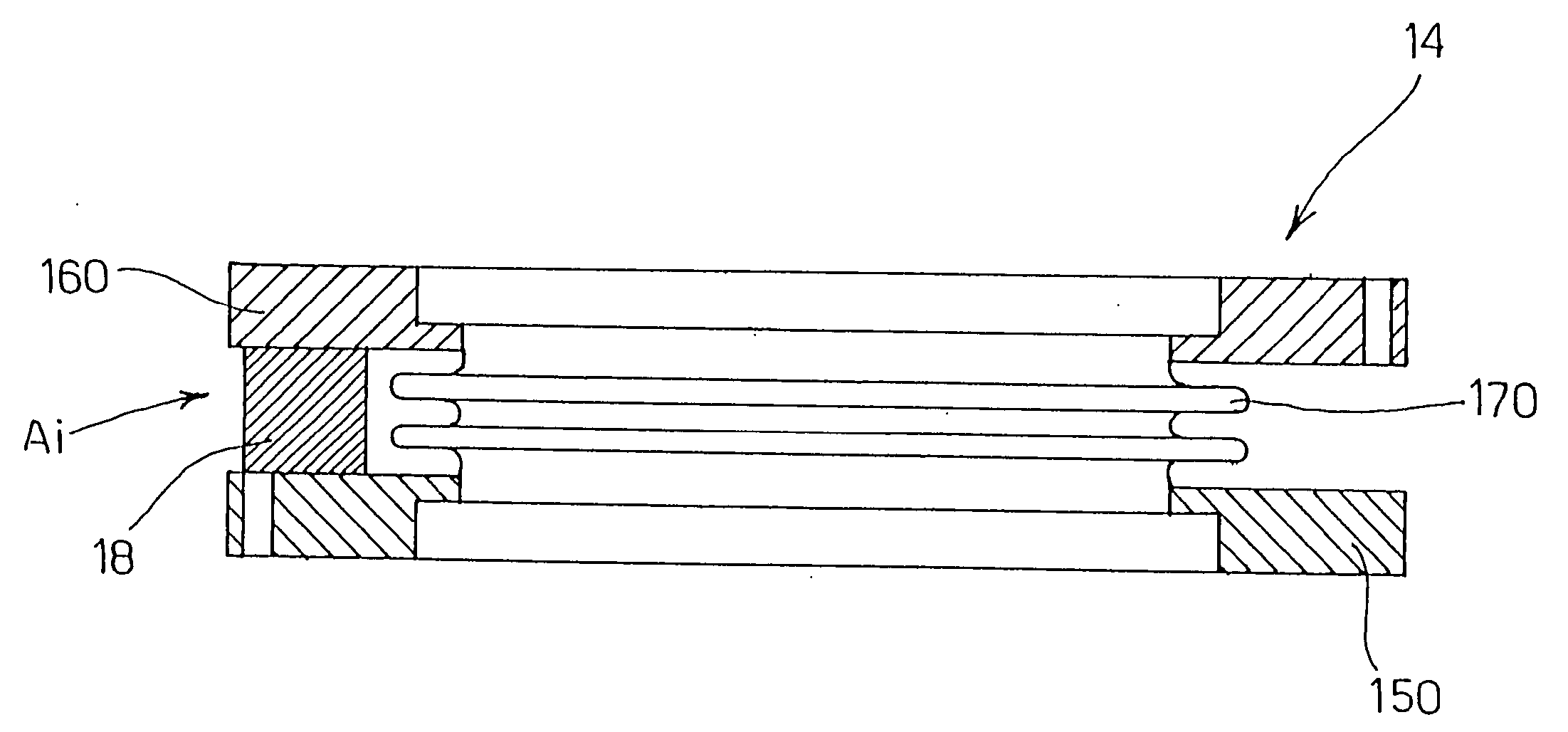
[0052]FIG. 5a shows part of a damper 24 of a vacuum pump according to the invention.
[0053] In this embodiment, flange 115 of the vacuum pump inlet port is directly coupled with counterflange 210 of a vacuum chamber through securing screws 20 uniformly distributed along the circumference of said flange 115, around centring ring 190 and the corresponding O-ring 195, and through corresponding securing nuts 21.
[0054] Piezoelectric actuators Ai are formed by cylindrical washers 28 mounted around stems 20a of securing screws 20, in contact with flange 115 on the one side and with counterflange 210 on the other side. Thus, the axial thrust (shown by arrows F2) of actuators 28 can be effective on the one side on the pump and on the other side on the vacuum chamber, thereby compensating for the axial vibrations measured onboard the pump and resulting in a reduction of the transmitted vibration.
[0055] In this second embodiment metal bellows 170 and the corresponding flanges 150, 160 can the...
PUM
 Abstract
Description
Claims
Application Information
 - R&D
- Intellectual Property
- Life Sciences
- Materials
- Tech Scout
- Unparalleled Data Quality
- Higher Quality Content
- 60% Fewer Hallucinations
Browse by: Latest US Patents, China's latest patents, Technical Efficacy Thesaurus, Application Domain, Technology Topic, Popular Technical Reports.
© 2025 PatSnap. All rights reserved.Legal|Privacy policy|Modern Slavery Act Transparency Statement|Sitemap|About US| Contact US: help@patsnap.com