Patterned electrospinning
a technology of electrospinning and patterned fibers, applied in the direction of dough shaping, manufacturing tools, melt spinning methods, etc., can solve the problem that the known electrospinning methods of polymer fibers exhibit limited control over the deposit of those fibers on the surfa
- Summary
- Abstract
- Description
- Claims
- Application Information
AI Technical Summary
Benefits of technology
Problems solved by technology
Method used
Image
Examples
example 1
[0048] A solution of polyethylene oxide polymer (“PEO”) and dimethyl formamide (“DMF”) solvent was prepared in glass bottles having a final concentration of about 12 weight percent of polymer. The bottle was sealed shut to prevent solvent evaporation. Dissolution was observed at room temperature and the solution was used for electrospinning.
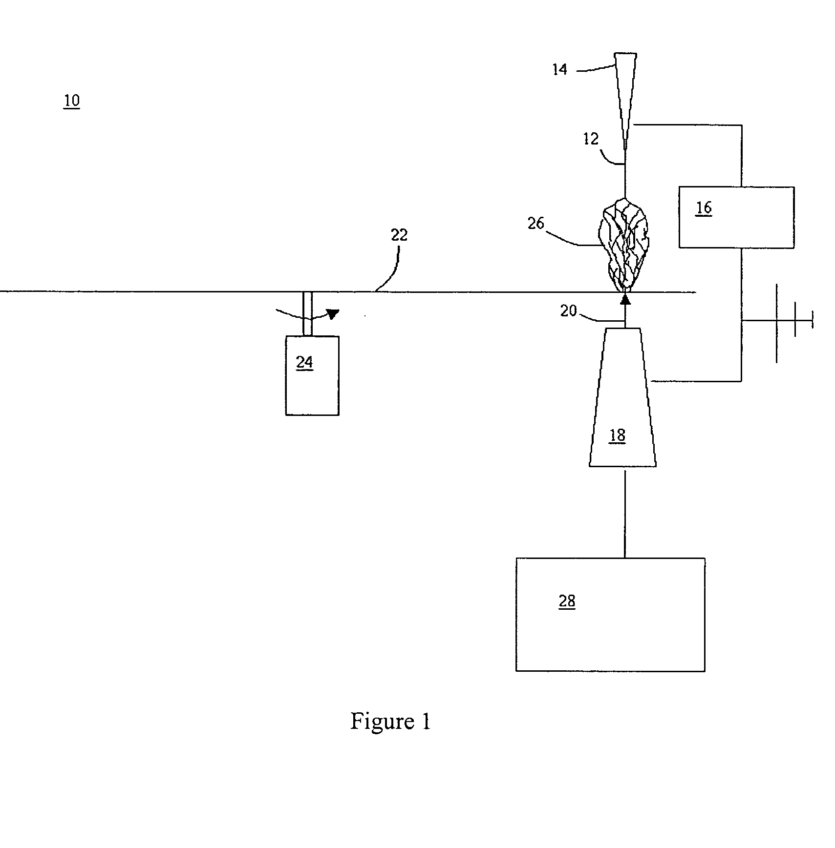
[0049] A movable counterelectrode having a circular 1 mm surface dimension was placed at a distance of about 15 cm from the syringe and perpendicular to the syringe tip. A sheet of Mylar® film was interposed between the syringe and the movable counterelectrode, which remain fixed at a distance from the syringe and perpendicular to the syringe tip. A 1.5 kV charge was supplied to the movable electric by a high voltage power supply, resulting in a concentration of electric charge being formed on the electrode. The tip of the syringe was grounded. The spinning process was carried out at room temperature, and the spinning rate was controlled by adju...
example 2
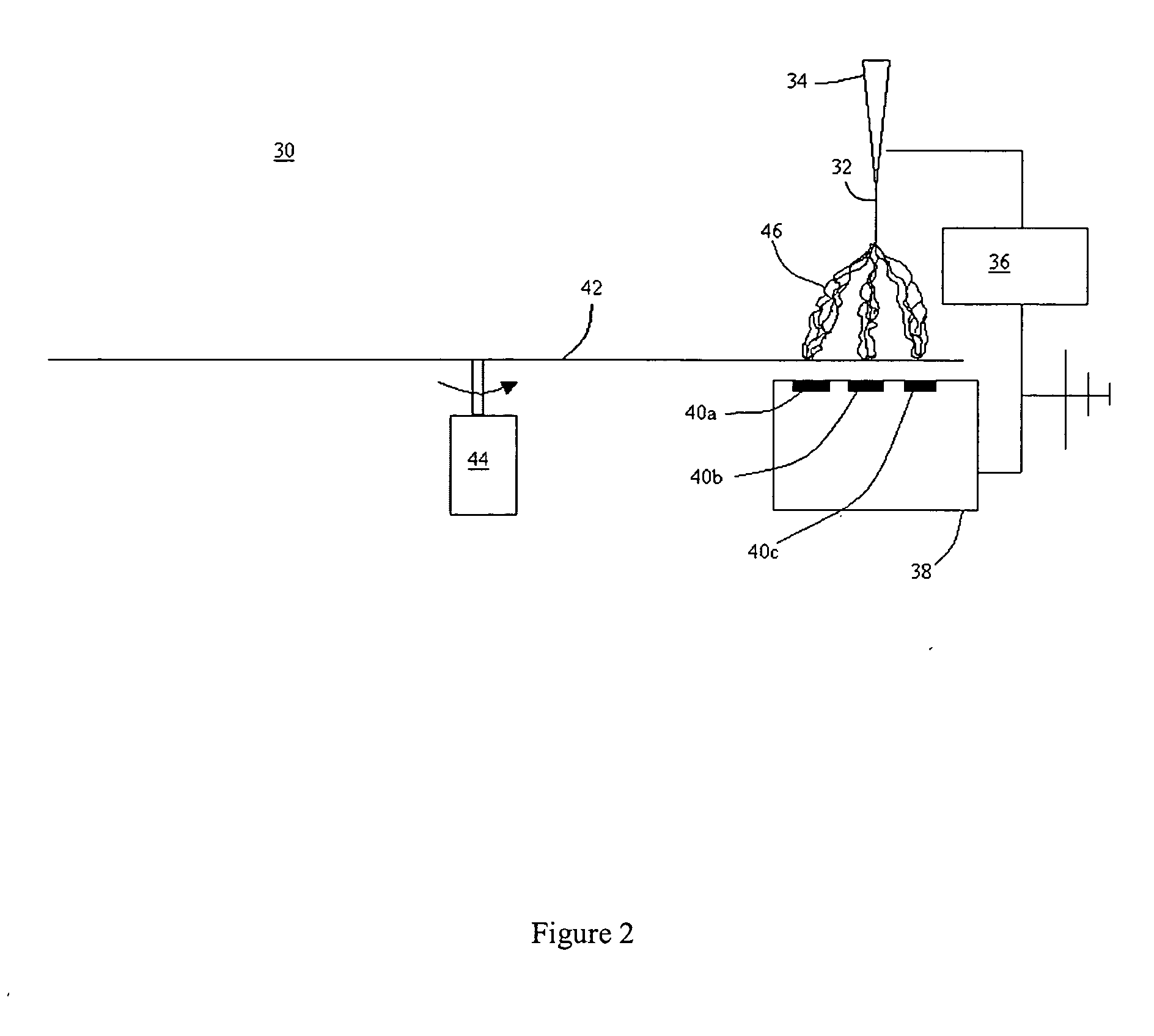
[0051] The electrospinning of Example 1 was repeated, except that the movable electrode was moved in the x-y plane to deposit the electrospun fibers on the Mylar® film to form a patterned structure having a selected predetermined specific surface pattern. A X-Y programable controller was used to control the movement of the movable electrode to form a surface pattern characterized by multiple fiber aggregations having the appearance of circular spots on in the Mylar® film, with the spots essentially separated from each other. The areas between the spots also contained fiber deposited during the movement of the electrode from spot to spot, but had considerable lesser depth than the spots.
[0052] A control example was performed using the same electrospinning process except that a large surface area electrode having a smooth surface was used and the electrospun fibers were deposited on the Mylar® film in a random manner. Using the same amount of electrospun fiber, the deposited fiber fo...
example 3
[0053]FIG. 6 is a photograph of electrospun fibers and a pattern of fiber aggregation created using the articles and methods of this invention. The fibers were deposited on a Kapton® polyimide film using a continuous metal sheet with 0.25 inch diameter holes as the ground electrode.
PUM
| Property | Measurement | Unit |
|---|---|---|
| velocity | aaaaa | aaaaa |
| diameter | aaaaa | aaaaa |
| electric field | aaaaa | aaaaa |
Abstract
Description
Claims
Application Information
 - R&D
- Intellectual Property
- Life Sciences
- Materials
- Tech Scout
- Unparalleled Data Quality
- Higher Quality Content
- 60% Fewer Hallucinations
Browse by: Latest US Patents, China's latest patents, Technical Efficacy Thesaurus, Application Domain, Technology Topic, Popular Technical Reports.
© 2025 PatSnap. All rights reserved.Legal|Privacy policy|Modern Slavery Act Transparency Statement|Sitemap|About US| Contact US: help@patsnap.com


