
Apparatus for Producing a Fire Special Effect

a special effect and apparatus technology, applied in the field of special effects devices, can solve the problems of complicating the design of the console, preventing the achievement of uniform or desired steam density over the entire length of the console,

Inactive Publication Date: 2005-05-12
TECHNIFEX PRODS
View PDF12 Cites 7 Cited by
  • Summary
  • Abstract
  • Description
  • Claims
  • Application Information

AI Technical Summary

Benefits of technology

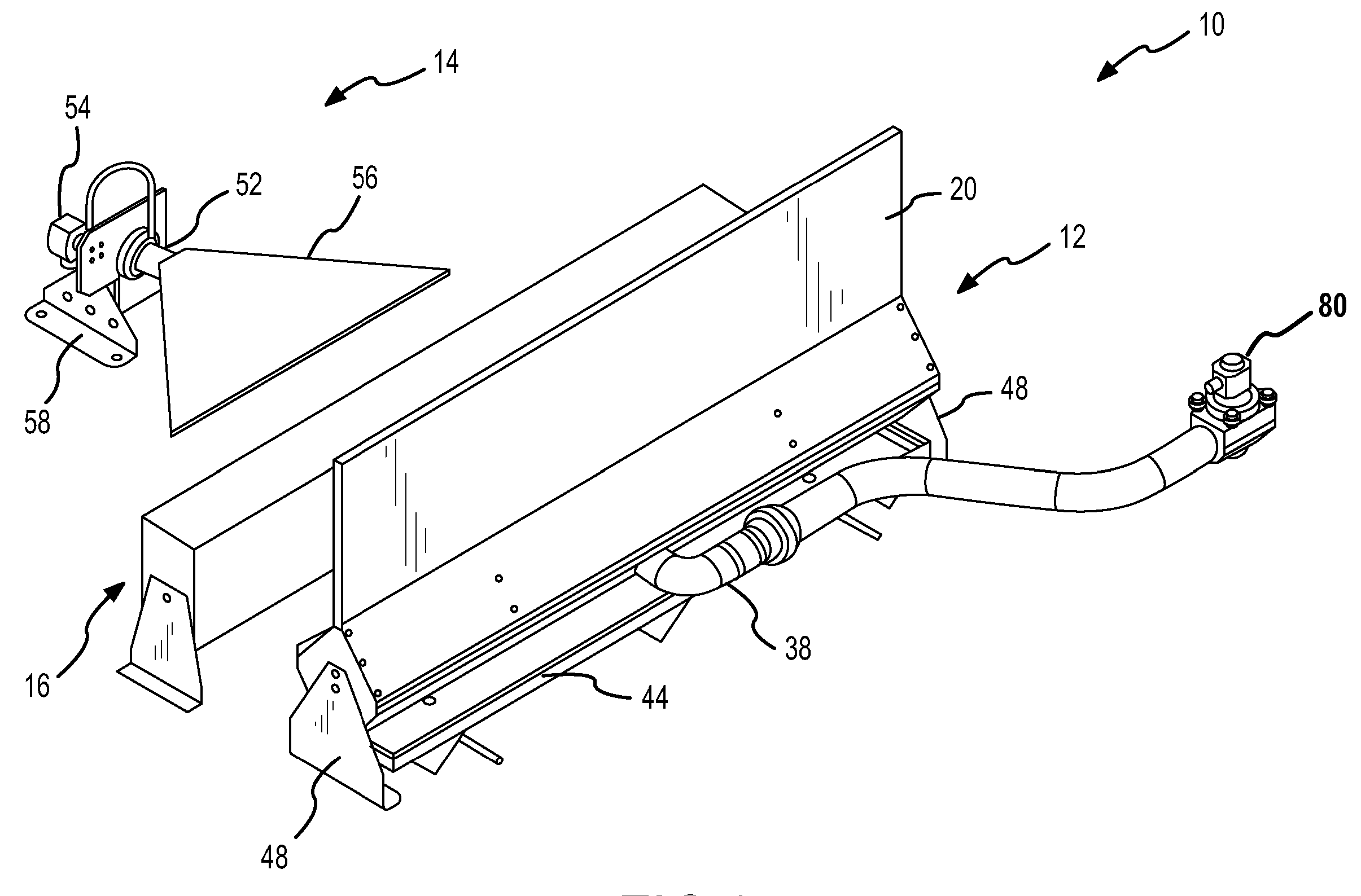
[0005] The present invention is directed to a special effect device for producing a simulated flame or fire effect. In one embodiment, the special effect device comprises a console for producing a curtain of steam, which is probably more accurately characterized as a fog, adjacent to an outlet slot or port of a housing. The device further comprises an air modulator for producing a stream of air that is used to vary or modulate the curtain of steam produced by the console. The rising steam in the curtain of steam and the modulation of the curtain of steam closely mimics the dynamic action of an actual flame or fire. The special effect device further comprises lighting that directs a flood of appropriately colored light onto the modulated or undulating curtain of steam. The interaction of the flood of light with the moving curtain of steam yields a simulated flame or fire effect.
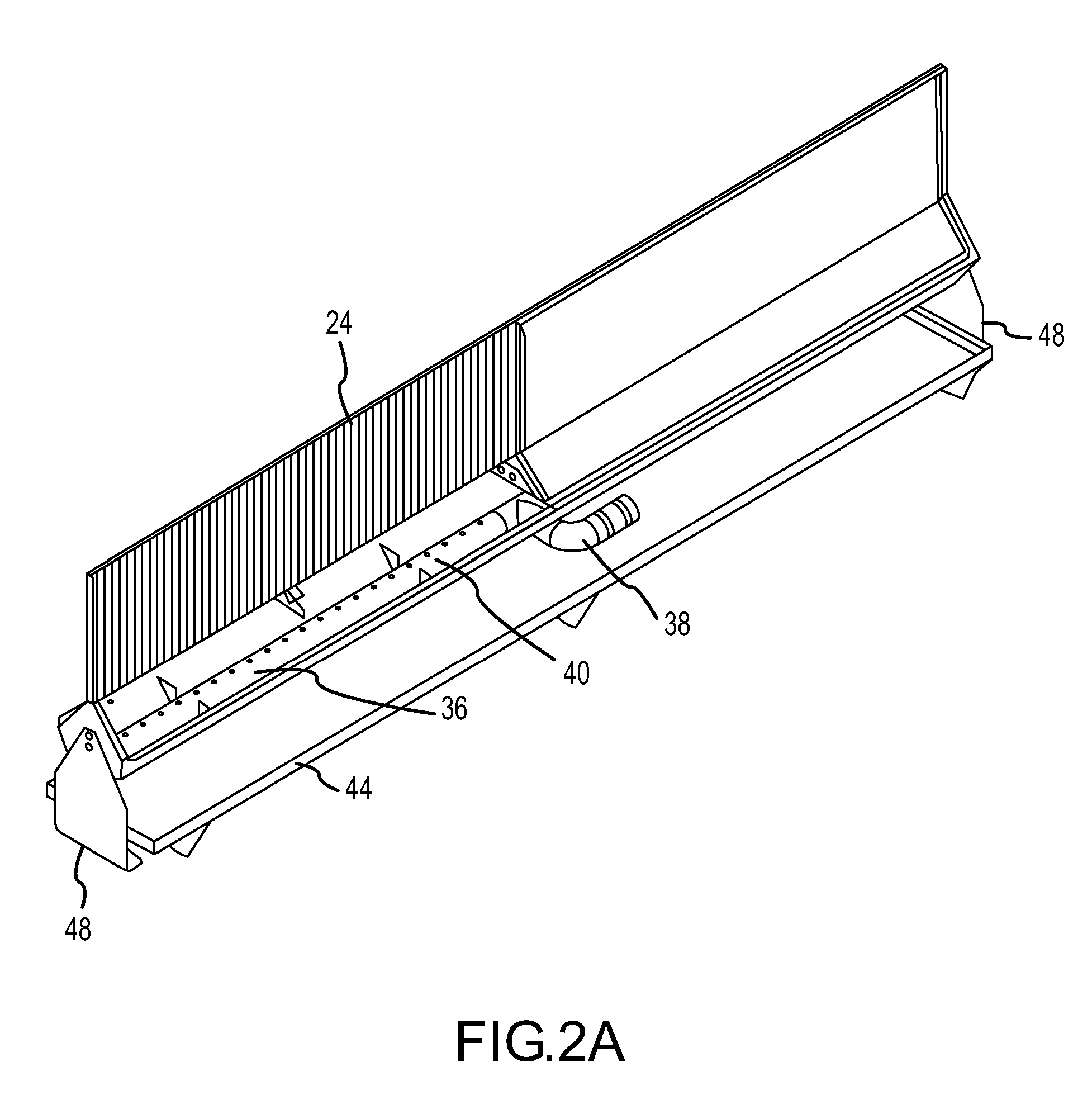
[0006] In one embodiment, the console comprises a steam manifold that contributes to the production of a curtain of steam with a substantially uniform or desired steam density. In one embodiment, the steam manifold has an elongated body with multiple output ports distributed along the length of the elongated body so a curtain of steam is produced adjacent to the outlet slot for substantially the length of the console. The steam manifold further comprises an inlet port for receiving steam that is located between the ends of the elongated body. Locating the inlet port in this manner permits several such consoles to be placed end-to-end and, because each console is producing a curtain of steam for substantially the length of the console, a curtain of steam is produced over the extent of the consoles that has a uniform or desired steam density. In contrast, if consoles were utilized in which the steam manifold of one console had to be connected to the steam manifold of the next console by a coupler located between the consoles, there would likely be significant gaps between the curtains of steam produced by each console, thereby preventing a uniform or desired steam density from being achieved over the extent of the consoles. Further, even if a string of consoles could be coupled together so as to eliminate or substantially reduce any gaps in the resulting steam curtain, the ability to achieve a uniform or desired steam density over the extent of the string of consoles is facilitated by locating the inlet port for the steam manifold between the ends of the elongated body of the manifold. To elaborate, if the inlet port was not located between the ends of the elongated body of the manifold, a string of consoles would be coupled to one another and steam would be fed into the string of consoles from one or both of the consoles at the end of the string. In such a configuration, the pressure drop along the length of the string would have to be taken into account to achieve a uniform or desired steam density along the length of the string. This significantly complicates the design of a console, i.e., the need to take into account the effect of the other consoles in a string of consoles. In contrast, by placing an inlet port between the ends of the elongated body of the steam manifold, at least for consoles that are not the end consoles of a string, consoles can be independently designed to produce a uniform or desired steam density without having to take into account the effect of other consoles that are to be in a string of consoles.
[0008] Another embodiment of the special effect device includes a console for producing a relatively tall curtain of steam, which allows a fire of flame illusion to be produced over a broad range of heights. In one embodiment, the console comprises a housing with an outlet slot or port for venting the steam that produces the curtain or screen of steam. A steam manifold located within the housing employs an outlet structure that presents a relatively low resistance to the flow of steam. As a consequence, the outlet structure of the manifold contributes to the height of the curtain of steam produced adjacent to the outlet port of the housing when the special effect device is in operation. In one embodiment, the steam manifold comprises an elongated body and the outlet structure is a series of holes located between the ends of the elongated body. The holes present a relatively low resistance to the flow of steam when compared to fan nozzles. To elaborate, fan nozzles force any steam passing through the nozzle to traverse a 90 degree turn that reduces the velocity of the steam exiting the nozzle. This reduction in velocity means that the fan nozzle exhibits or is characterized by a relatively high resistance to the flow of steam. A hole or other outlet structure does not require the steam to make a 90 degree turn. Consequently, the steam exits the outlet port of the housing at a higher velocity.
[0009] In a further embodiment, the console comprises a housing with air entrainment holes that contribute to the density of the curtain of steam produced adjacent to the outlet slot of the housing during operation. By producing a denser curtain of steam, the visibility of the resulting fire effect is improved or enhanced. The air entrainment holes are located below the outlet structure of a steam manifold located within the housing. In one embodiment, the air entrainment holes are located as far below the outlet structure of the steam manifold as possible.
[0018] A further embodiment of the theatrical smoke-based device comprises a housing, theatrical smoke and gas emission manifolds that are each substantially located within the housing, an air modulator, and a lighting system. Each of the manifolds comprises an inlet port that is located between the ends of the manifold. By locating the inlet ports in this manner, two or more devices can be cascaded together and used to produce a simulated flame or fire effect over substantially the entire length of the devices. In one embodiment, the inlet ports are located at or near the midpoints of the manifolds to facilitate the production of a substantially uniform curtain of theatrical smoke.

Problems solved by technology

In contrast, if consoles were utilized in which the steam manifold of one console had to be connected to the steam manifold of the next console by a coupler located between the consoles, there would likely be significant gaps between the curtains of steam produced by each console, thereby preventing a uniform or desired steam density from being achieved over the extent of the consoles.
This significantly complicates the design of a console, i.e., the need to take into account the effect of the other consoles in a string of consoles.

Method used


Image

  • Apparatus for Producing a Fire Special Effect
  • Apparatus for Producing a Fire Special Effect
  • Apparatus for Producing a Fire Special Effect

Examples


second embodiment

[0090] With reference to FIG. 14, a special effect device, hereinafter referred to as device 250, for producing a simulated flame or fire effect using a cloud of steam and that is particularly useful in an application in which a target viewer is typically able to inspect the device from relatively close range, the application in this case being a sconce. The device 250 is comprised of a steam console 252, an air modulator 254, and a lighting system 256. The device 250 is further comprised of a cover 258 that prevents a target viewer from seeing the steam console 252, air modulator 254, and lighting system 256 that are used to produce the simulated flame or fire effect. The fans associated with the air modulator 254 and the lights associated with the lighting system 256 are, like the comparable elements in device 200, operatively attached to the housing of the steam console 252 by support structures. Further comprising the device 250 is a mounting panel 260 that allows the device 250...

third embodiment

[0092] With reference to FIG. 15, a special effect device, hereinafter referred to as device 280, for producing a simulated flame or fire effect using a cloud of steam and that is particularly useful in an application in which a target viewer is typically able to inspect the device from relatively close range and from 360 degrees, the application in this case being a torchiere. The device 280 is comprised of a steam console 282, an air modulator 284, and a lighting system 286. The device 280 is further comprised of a cover 288 that prevents a target viewer from seeing the steam console 282, air modulator 284, and lighting system 286 that are used to produce the simulated flame or fire effect. The exterior of the cover 288 may be treated to produce a theme effect. For example, the exterior of the cover 288 may be treated so as to appear to be a brass or copper bowl to the target viewer. In the illustrated embodiment, the dimensions of the steam console 282 are such that the fans asso...

fourth embodiment

[0094] With reference to FIG. 16, a special effect device, hereinafter referred to as device 300, for producing a simulated flame or fire effect using a cloud of steam and that is particularly useful in an application in which a target viewer is typically able to inspect the device from relatively close range, the application in this case being a medieval torch. The device 300 is comprised of a steam console 302, an air modulator 304, and a lighting system 306. The device 300 is further comprised of a cover 308 that prevents a target viewer from seeing the steam console 282, air modulator 284, and lighting system 286 that are used to produce the simulated flame or fire effect. The cover 308 is comprised of a first cover portion 310 that is designed to resemble the wick portion of the torch and a second cover portion 312 that is designed to resemble the wooden handle portion of the torch. In the illustrated embodiment, the dimensions of the steam console 302 are such that the fans as...


PUM


Abstract

In one embodiment, the present invention provides a device for producing a fire special effect that is suitable for applications in which the viewers of the simulated flame are able inspect the device from relatively close range and / or from a number of perspectives. For example, the device can be used as a torchiere or wall sconce.

Description

CROSS-REFERENCE TO RELATED APPLICATIONS [0001] This application is a continuation-in-part of U.S. patent application Ser. No. 10 / 249,949, filed May 21, 2003, which is a continuation-in-part of U.S. patent application Ser. No. 10 / 063,264, filed Apr. 4, 2002, which applications are incorporated by reference into this application in their entireties.FIELD OF THE INVENTION [0002] The present invention is directed to a special effect device and, in particular, to a device for producing a simulated fire or flame special effect. BACKGROUND OF THE INVENTION [0003] The use of a simulated fire or flame is desirable in many applications. For instance, in many theme park attractions (e.g., volcano, battle scene and disaster scenes), the use of a simulated flame or fire is preferred relative to a real flame or fire for a number of reasons. To elaborate, a real flame or fire must typically be located a substantial distance from the audience to prevent members of the audience from getting burned. ...

Claims


Application Information

Patent Timeline
Patent Type & Authority Applications(United States)
IPC IPC(8): A63J5/02
CPCA63J5/023
Inventor STARR, JOSEPH W.
Owner TECHNIFEX PRODS
Learn More