
Constant velocity joint vent valve

a constant velocity joint and vent valve technology, applied in the direction of functional valve types, couplings, engine diaphragms, etc., can solve the problems of internal damage and destruction of the joint, loss of sealing ability, and the blockage of the vent hole by lubricating grease, so as to prevent the escape of grease

Active Publication Date: 2005-05-12
GKN DRIVELINE NORTH AMERICA
View PDF8 Cites 13 Cited by
  • Summary
  • Abstract
  • Description
  • Claims
  • Application Information

AI Technical Summary

Benefits of technology

"The present invention provides a vent valve for constant velocity joints that protects the internal joint cavity and grease from overpressure and external contaminants. The vent valve allows expanding internal gases to vent to the external environment while preventing external contaminants from entering. The vent valve is self-cleaning and resistant to plugging. The vent valve also allows for the reintroduction of gas back into the constant velocity joint chamber upon cooling or a decrease of internal pressure in the joint. The permeable material will further lessen the build-up of grease upon the vent valve."

Problems solved by technology

This sealing and protection of the constant velocity joint is necessary because contamination of the inner chamber may cause internal damage and destruction of the joint.
If the pressure build-up is allowed to reach a critical state, the boot, protecting the joint from contaminants and water, may crack and deteriorate, or blow out, thus losing its sealing capability.
In addition, the vent hole may become blocked by the lubricating grease while the constant velocity joint is rotating or in a dynamic state.
If the vent hole becomes blocked, the internal pressure may build up causing the joint seal to fail due to a ruptured boot or other catastrophe.
Furthermore, the constant velocity joint, after running for long periods of time, creates very high temperatures along with high pressures which are vented through the current vent holes.
However, if the constant velocity joint is submerged, splashed, or saturated in water or other contaminants, the water will, via vacuum caused by the temperature differential or by gravity, be sucked into the constant velocity joint chamber, thus contaminating the grease lubricant and reducing the life of the constant velocity joint.
Therefore, the ingress of water and other contaminants and egress of joint grease through the vent hole may reduce the life expectancy for the constant velocity joints.

Method used


Image

  • Constant velocity joint vent valve
  • Constant velocity joint vent valve
  • Constant velocity joint vent valve

Examples


Embodiment Construction

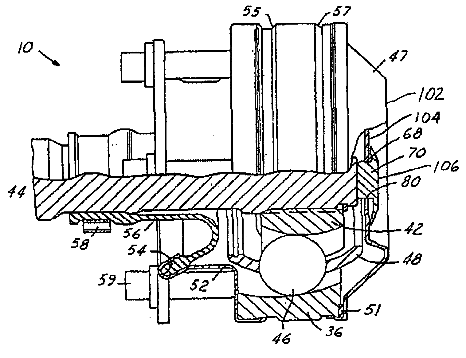
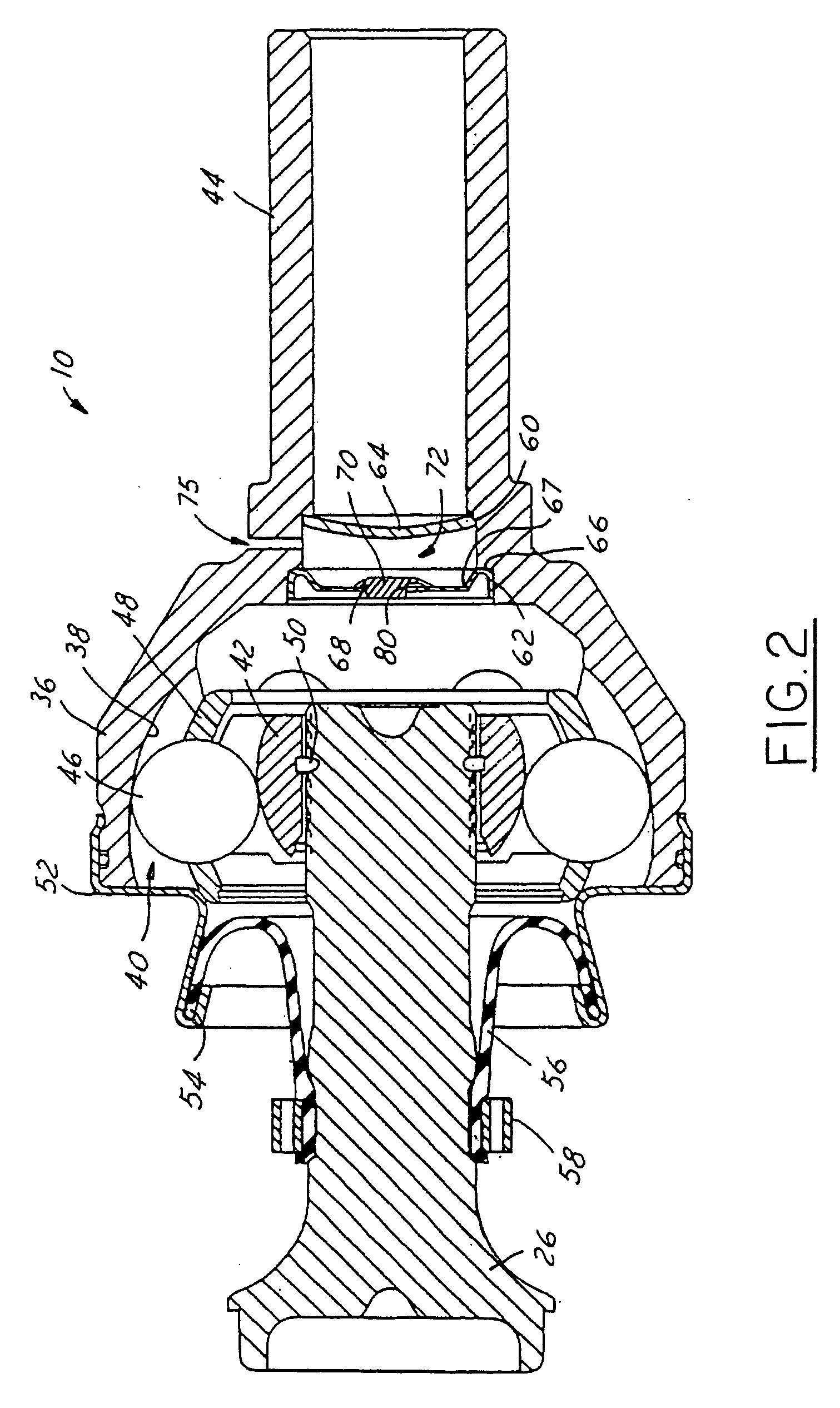
[0018] Referring to the drawings, a constant velocity joint 10 including a vent valve according to the present invention is shown. It should be noted that any type of constant velocity joint such as a plunging tripod, a fixed tripod, etc. having any style such as a monoblock, a disk, a Rzeppa, etc. may be used in combination with to the present vent valve. The vent valve of the present invention provides a novel and improved method of venting the joint to prevent grease from plugging the vent valve, and allows pressurizing the internal constant velocity joint chamber to bring it into pressure equilibrium with the external environment.

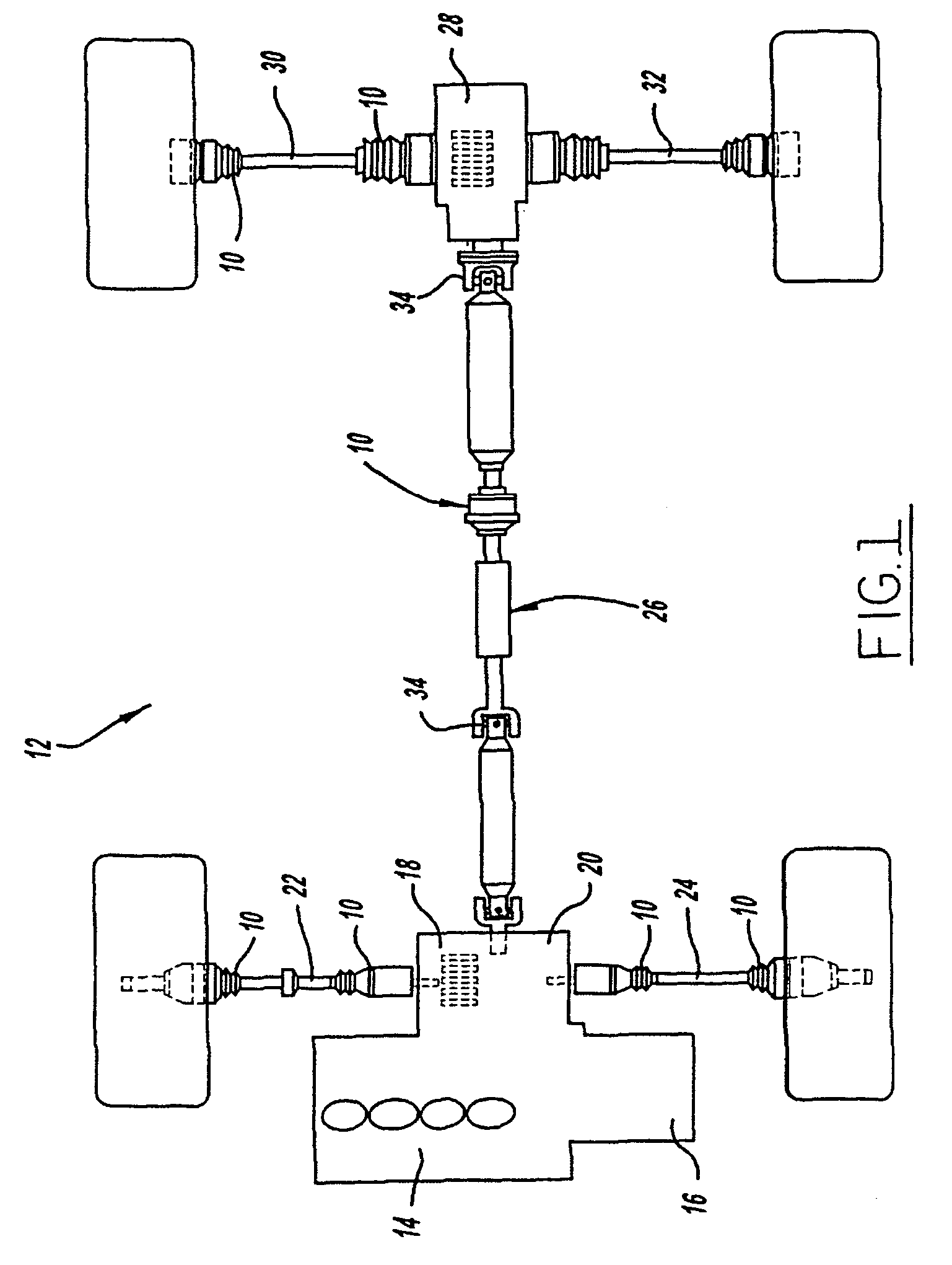
[0019]FIG. 1 shows a plan view of an all wheel drive vehicle drive line wherein the present vent valve may be used to advantage. The drive line 12 shown in FIG. 1 is a typical all wheel drive vehicle driveline. However it should be noted that other vehicle drivelines employing vented constant velocity joints can also be improved with the present vent v...


PUM


Abstract

A vent valve for use in a constant velocity joint having a vent aperture in communication with a joint chamber comprises a body having a first end and a second end and at least one flat extending therebetween; and an umbrella shaped flexible retention cap disposed adjacent the first end of the body and the at least one flat. The retention cap is operative in a normally closed position to cover the at least one flat and seal the joint from external contaminants, and in response to internal pressure created in the joint cavity, functions to bellow outward and expose the at least one flat to permit air to escape from the chamber. The at least one flat includes a straight-line vent to clean the grease off and away from the vent valve. The vent valve can be made from single or multiple materials, having porous and non-porous properties.

Description

TECHNICAL FIELD [0001] The present invention generally relates to constant velocity joints and more particularly, to a vent for a constant velocity joint. BACKGROUND OF THE INVENTION [0002] Constant velocity joints are common components in automotive vehicles. Typically, constant velocity joints are employed where transmission of a constant velocity rotary motion is desired or required. Common types of constant velocity joints are a plunging tripod, a fixed tripod, a plunging ball joint and a fixed ball joint. These types of joints currently are used in front wheel drive vehicles, or rear wheel drive vehicles, and on the propeller shafts found in rear wheel drive, all wheel drive and four wheel drive vehicles. These constant velocity joints are generally grease lubricated for life and sealed by the use of sealing boots when used on drive shafts. Thus, constant velocity joints are sealed in order to retain grease inside the joint while keeping contaminants and foreign matter, such as...

Claims


Application Information

Patent Timeline
Patent Type & Authority Applications(United States)
IPC IPC(8): F16D3/20F16J3/02F16D3/223F16D3/84
CPCF16D3/223Y10T464/10Y10S464/902F16D2003/2232Y10T137/789Y10T137/784F16D2300/0212F16D2003/846F16D3/843
Inventor WANG, SHEN-LING ALLEN
Owner GKN DRIVELINE NORTH AMERICA
Learn More