
System and method for product display, arrangement and rotation

Inactive Publication Date: 2005-05-12
CLOSE JAMES GARTH
View PDF18 Cites 128 Cited by
  • Summary
  • Abstract
  • Description
  • Claims
  • Application Information

AI Technical Summary

Benefits of technology

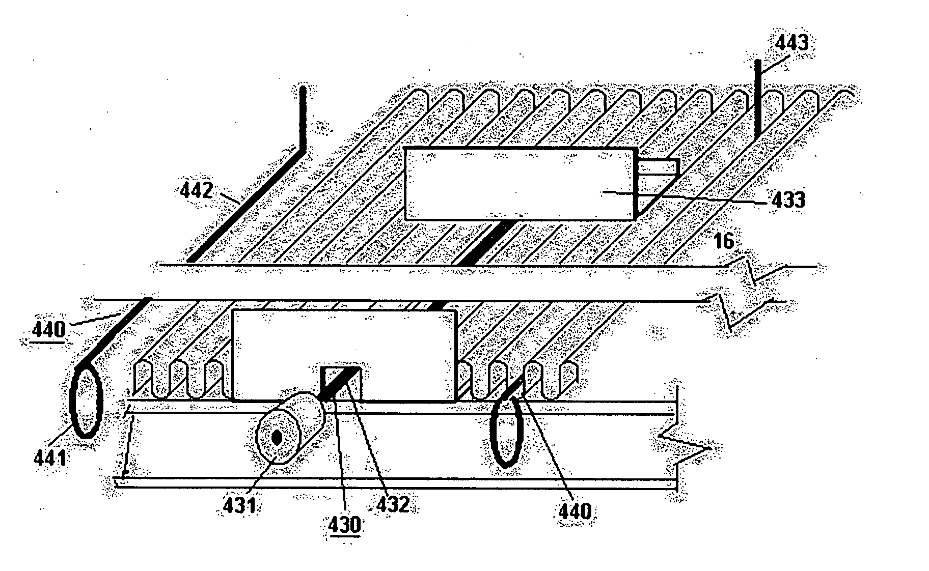
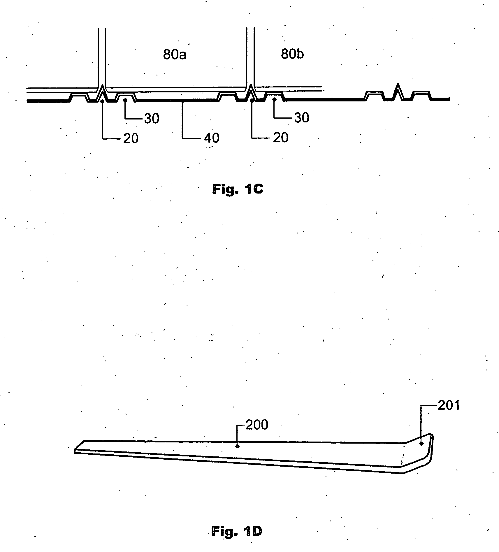
[0016] Row dividers may be provided by the ridges themselves, such as with a stepped ridge, or may be provided by divider partitions inserted into recesses in the ridges or between ridges. In some embodiments, the shape of the ridges is sufficient to separate rows of merchandise without additional partitions. For many types of merchandise which have rounded or indented profiles in the lower portion of the container, a stepped ridge profile can be selected to fit into the recess formed between adjacent rows of containers, so that row division may be accomplished without requiring the additional shelf width of partition inserts. For retailers such as grocery stores that have precisely defined merchandising plans, this aspect of the invention permits the display base to be adopted without modification to the merchandising scheme.
[0021] Advantages of the current invention include the low cost of the display base, such as provided by thermoforming or vacuum molding the base, efficient packaging, and low shipment cost. The base is also very easy to cut to desired size and to install on a shelf without special tools. The base can typically be cut with scissors or a box knife. The base will work with various display shelf depths, and with various sizes of merchandise including product containers such as cans, bottles, and bags.
[0026] Inventory, such as restocking is assisted by observing the length of the pull device, which provides a measure of available display space behind the containers. In this way, the stocker does not need to visually observe the row depth, and the shelve height can be lower than what is required for visual inspection.

Problems solved by technology

Customers typically remove products from the front of a display shelf, and products remaining toward the rear of display shelves are often difficult to reach.

Method used


Image

  • System and method for product display, arrangement and rotation
  • System and method for product display, arrangement and rotation
  • System and method for product display, arrangement and rotation

Examples


Embodiment Construction

Display Base and Pull Straps for Grocery Display

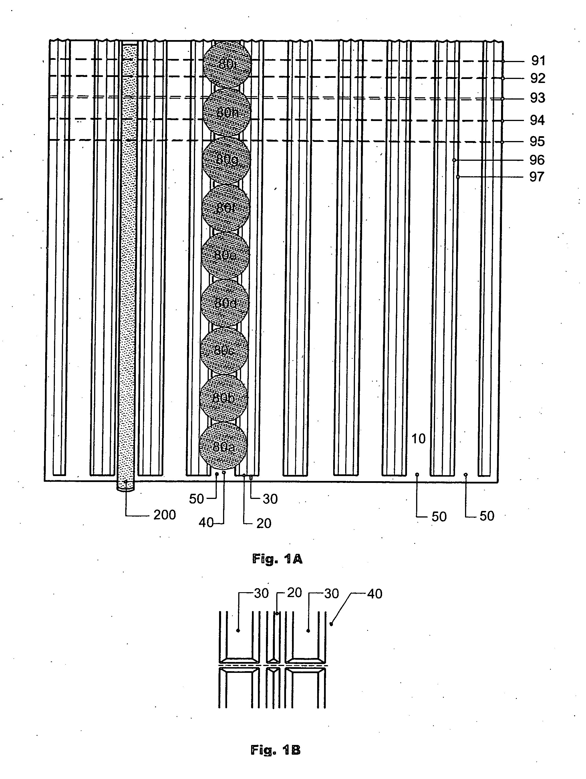
[0074] Referring now to FIG. 1A which is a top view of an embodiment of the current invention, several containers 80a-80i, such as soup cans are placed in one row 50 of a display base 10. Alternate embodiments support other sizes of cans, boxes, bags, and loose merchandise.

[0075] In this embodiment, the base may be a plastic sheet which may be bent or scored along one of several depth adjustment lines 91-97 at the rear of the base. This permits the base to be sized for standard grocery store shelve depths of 18, 19, 20, 21, 22, 23, or 24 inches. The rear of the base may be either bent up or may be bent and scored or cut to remove the excess material. The bending is typically performed by laying the base upside down and backwards on a shelf so that the base may be bent at an appropriate bend line. After bending, the extra base material may be left in a bent position or may be removed such as by cutting it off with a box blade.

[0076] ...


PUM


Abstract

A device, system, and method for manually arranging products on a display shelf. A plastic ridged base may be cut to a desired display shelf width along preformed notches and then be placed on the display shelf. Excess base width may serve as a rear backing element to support row partitions. The ridges support merchandise and permit a pull member to rest between ridges. The pull member may be manually pulled to bring merchandise to the front of a row. The ridges may be universal, or may be of specific dimensions for items such as soup cans or baby food jars. Narrow base sections may be extruded and snapped together to form a desired base unit width. A spring or elastic active alignment device may be used on the base to move display items forward on a shelf.

Description

RELATED APPLICATIONS [0001] This application is a continuation in part of U.S. patent applications No. 10 / 392,162 filed March 18, 2003 and claims priority from that application. [0002] This application is related to U.S. provisional patent applications No. 60 / 290,969 filed on May 14, 2002; No. 60 / 292,441 filed on May 19, 2002; and No. 60 / 400,976 filed on Jul. 28, 2002; and claims priority from those applications.BACKGROUND OF THE INVENTION [0003] 1. Field of the Invention [0004] The invention relates to the display, arrangement and rotation of products such as those packaged in bottles, jars, cans, and boxes, and more particularly to an improved product display, arrangement and rotation system and method in which products displayed on a display shelf can easily be arranged or rotated to have the products' expiration dates kept safely up to date and to conveniently position the products manually near the front edge of the shelves for improved visual exposure and effortless selection ...

Claims


Application Information

Patent Timeline
IPC IPC(8): A47F1/12A47F7/28
CPCA47F1/12A47F7/28A47F1/126
Inventor CLOSE, JAMES GARTH
Owner CLOSE JAMES GARTH
Learn More